


Chapter 3
3-4
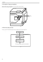
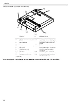
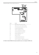
3.3.2 Configration of Image processing Module
0020-4213
The main image processing of this equipment is executed by the Main controller PCB (main).
Following is the related module configuration.
F-3-4
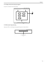
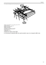
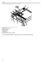
3.3.3 Reader entry Image processing
0020-4214
The image processor PCB performs the image processing to the image data read at the contact image sensor.
F-3-5
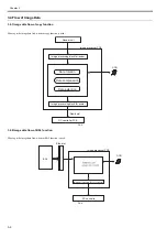
DDR
Reader controller PCB
-image memory
-Temporary strage of program
Image Processor PCB
DC controller PCB
Reader Unit
This performs the image
processing against the
image data read at the reader unit
Reader entry image processing area
This performs the image processing
to output the image to printer
Printer output image processing area
To the compression/expansion/edit processing block
-
correction
- Mirror image processing
- Magnification chage processing
- Brightness density correction
- Even out variation
Image processor PCB
Reader unit
Содержание iR2422 series
Страница 1: ...May 12 2014 Service Manual iR2422 2420 2320 2318 Series...
Страница 2: ......
Страница 6: ......
Страница 16: ...Contents...
Страница 17: ...Chapter 1 Introduction...
Страница 18: ......
Страница 20: ......
Страница 50: ......
Страница 51: ...Chapter 2 Installation...
Страница 52: ......
Страница 54: ......
Страница 58: ...Chapter 2 2 4 7 Left cover front 15 Right cover upper 8 Manual feed tray 16 Right cover lower...
Страница 62: ...Chapter 2 2 8 8 Manual feed tray 16 Right cover lower...
Страница 64: ...Chapter 2 2 10 8 Manual feed tray 16 Right cover lower...
Страница 89: ...Chapter 2 2 35...
Страница 90: ......
Страница 91: ...Chapter 3 Main Controller...
Страница 92: ......
Страница 94: ......
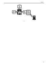
Страница 97: ...Chapter 3 3 3 F 3 3 SEND FAX PullScan E Mail BDL Print PC Original Copy A A A Print output Scan Image data...
Страница 102: ......
Страница 103: ...Chapter 4 Original Exposure System...
Страница 104: ......
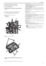
Страница 135: ...9 Remove the reader heater left 1 Connector 2 1 pc Screw 3 1 pc F 4 73 2 3 1...
Страница 136: ......
Страница 137: ...Chapter 5 Laser Exposure...
Страница 138: ......
Страница 140: ......
Страница 148: ...Chapter 5 5 8...
Страница 149: ...Chapter 6 Image Formation...
Страница 150: ......
Страница 152: ......
Страница 165: ...Chapter 7 Pickup Feeding System...
Страница 166: ......
Страница 192: ...Chapter 7 7 24...
Страница 193: ...Chapter 8 Fixing System...
Страница 194: ......
Страница 196: ......
Страница 207: ...Chapter 9 External and Controls...
Страница 208: ......
Страница 229: ...Chapter 10 Maintenance and Inspection...
Страница 230: ......
Страница 232: ......
Страница 235: ...Chapter 11 Standards and Adjustments...
Страница 236: ......
Страница 238: ......
Страница 240: ...Chapter 11 11 2...
Страница 241: ...Chapter 12 Correcting Faulty Images...
Страница 242: ......
Страница 244: ......
Страница 256: ......
Страница 257: ...Chapter 13 Self Diagnosis...
Страница 258: ......
Страница 260: ......
Страница 269: ...Chapter 14 Service Mode...
Страница 270: ......
Страница 272: ......
Страница 287: ...Chapter 15 Upgrading...
Страница 288: ......
Страница 290: ......
Страница 295: ...Chapter 16 Service Tools...
Страница 296: ......
Страница 297: ...Contents Contents 16 1 Service Tools 16 1 16 1 1 Special Tools 16 1 16 1 2 Oils and Solvents 16 1...
Страница 298: ......
Страница 300: ......
Страница 301: ...Chapter 17 Backup Data...
Страница 302: ......
Страница 303: ...Contents Contents 17 1 Backup Data 17 1...
Страница 304: ......
Страница 306: ......
Страница 307: ...May 12 2014...
Страница 308: ......


