


Chapter 6
6-7
6.6 Developing Unit
6.6.1 Outline
0020-4100
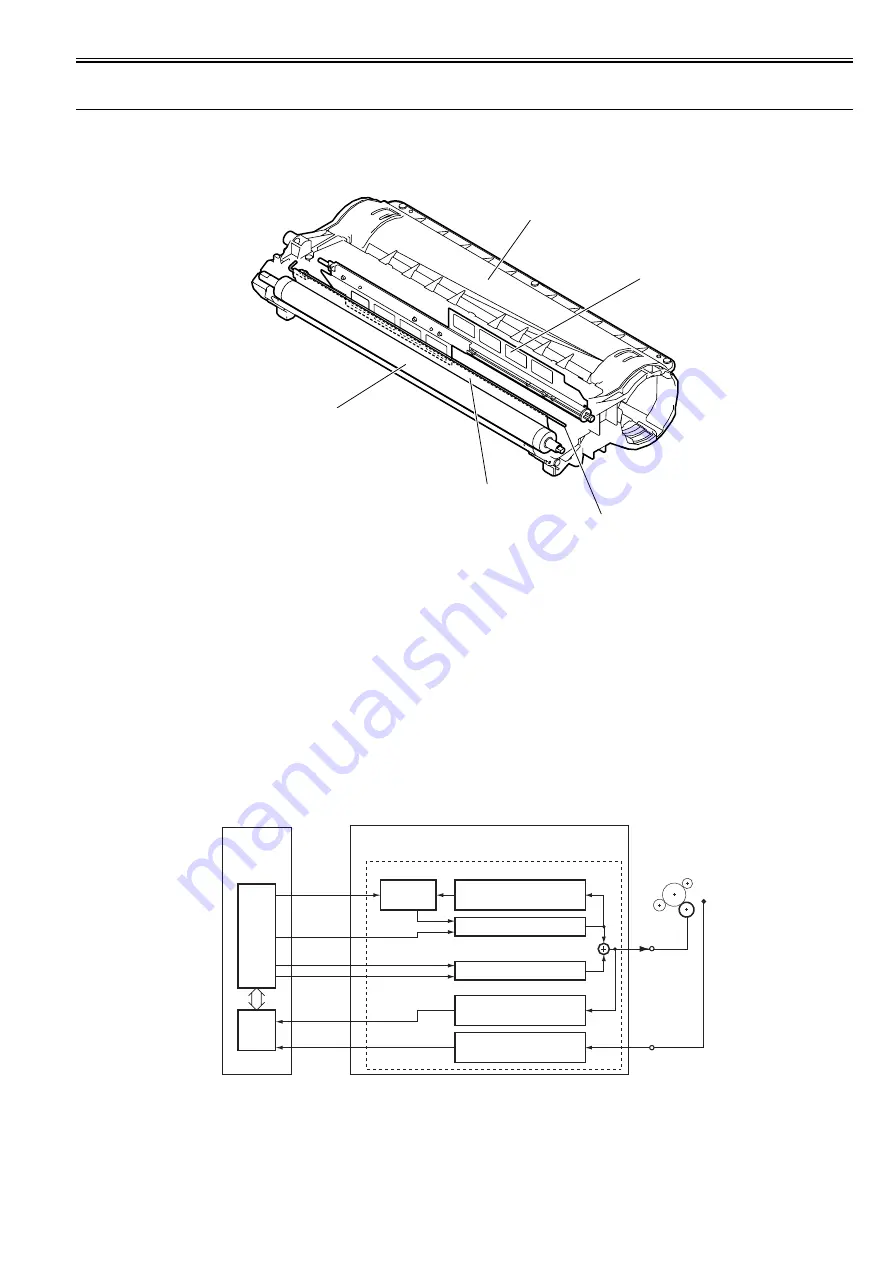
Major components of the developing assembly are as follows:
F-6-9
[1] Developing Assembly
[2] Stirring plate
[3] Antenna rod
[4] Developing blade
[5] Developing cylinder
6.6.2 Developing Bias Control
0020-4102
A DC bias and an AC bias are applied to the developing cylinder.
The ASIC on the DC controller PCB outputs the developing AC bias drive signal (/DVACFOT), developing AC bias ON/OFF signal (/DVACON), developing DC
bias drive signal (/DVDCFOT), and developing DC bias output level signal (/DVDCPWM) to apply the voltage generated by superimposing the developing AC
bias over the developing DC bias to the developing cylinder.
To prevent fogging of the drum, a DC bias higher than usual applied except during image formation and when the developing AC bias is applied for warm-up
rotation.
The developing DC bias is detected by the developing DC bias detection circuit, and is fed back to the DC generation circuit via the comparison circuit, thus con-
trolling the DC bias voltage. The developing DC bias voltage changes with the primary DC bias voltage according to the image density information sent from the
image processor PCB.
The remaining toner level is detected during warm-up rotation and when the developing AC bias is applied for printing. The remaining toner level detection signal
(TNRCHKT) sampled from the antenna (for remaining toner level check) in the developing assembly is compared with the reference signal (TNRCHKD) received
from the developing bias detection circuit.
F-6-10
[1]
[2]
[3]
[4]
[5]
JP7/JP8
JP1/JP2
TNRCHKT
TNRCHKD
/DVACFOT
/DVDCPWM
/DVDCFOT
To developing
cylinder
From remaining
toner level sensor
Developing bias circuit
ASIC
CPU
Developing DC bias
voltage detection circuit
Developing AC bias
current detection circuit
Remaining toner level
detection circuit
DC generation circuit
AC generation circuit
Comparison
circuit
/DVACON
Superimposition
High-voltage power supply PCB
DC controller
PCB
Содержание iR2422 series
Страница 1: ...May 12 2014 Service Manual iR2422 2420 2320 2318 Series...
Страница 2: ......
Страница 6: ......
Страница 16: ...Contents...
Страница 17: ...Chapter 1 Introduction...
Страница 18: ......
Страница 20: ......
Страница 50: ......
Страница 51: ...Chapter 2 Installation...
Страница 52: ......
Страница 54: ......
Страница 58: ...Chapter 2 2 4 7 Left cover front 15 Right cover upper 8 Manual feed tray 16 Right cover lower...
Страница 62: ...Chapter 2 2 8 8 Manual feed tray 16 Right cover lower...
Страница 64: ...Chapter 2 2 10 8 Manual feed tray 16 Right cover lower...
Страница 89: ...Chapter 2 2 35...
Страница 90: ......
Страница 91: ...Chapter 3 Main Controller...
Страница 92: ......
Страница 94: ......
Страница 97: ...Chapter 3 3 3 F 3 3 SEND FAX PullScan E Mail BDL Print PC Original Copy A A A Print output Scan Image data...
Страница 102: ......
Страница 103: ...Chapter 4 Original Exposure System...
Страница 104: ......
Страница 135: ...9 Remove the reader heater left 1 Connector 2 1 pc Screw 3 1 pc F 4 73 2 3 1...
Страница 136: ......
Страница 137: ...Chapter 5 Laser Exposure...
Страница 138: ......
Страница 140: ......
Страница 148: ...Chapter 5 5 8...
Страница 149: ...Chapter 6 Image Formation...
Страница 150: ......
Страница 152: ......
Страница 165: ...Chapter 7 Pickup Feeding System...
Страница 166: ......
Страница 192: ...Chapter 7 7 24...
Страница 193: ...Chapter 8 Fixing System...
Страница 194: ......
Страница 196: ......
Страница 207: ...Chapter 9 External and Controls...
Страница 208: ......
Страница 229: ...Chapter 10 Maintenance and Inspection...
Страница 230: ......
Страница 232: ......
Страница 235: ...Chapter 11 Standards and Adjustments...
Страница 236: ......
Страница 238: ......
Страница 240: ...Chapter 11 11 2...
Страница 241: ...Chapter 12 Correcting Faulty Images...
Страница 242: ......
Страница 244: ......
Страница 256: ......
Страница 257: ...Chapter 13 Self Diagnosis...
Страница 258: ......
Страница 260: ......
Страница 269: ...Chapter 14 Service Mode...
Страница 270: ......
Страница 272: ......
Страница 287: ...Chapter 15 Upgrading...
Страница 288: ......
Страница 290: ......
Страница 295: ...Chapter 16 Service Tools...
Страница 296: ......
Страница 297: ...Contents Contents 16 1 Service Tools 16 1 16 1 1 Special Tools 16 1 16 1 2 Oils and Solvents 16 1...
Страница 298: ......
Страница 300: ......
Страница 301: ...Chapter 17 Backup Data...
Страница 302: ......
Страница 303: ...Contents Contents 17 1 Backup Data 17 1...
Страница 304: ......
Страница 306: ......
Страница 307: ...May 12 2014...
Страница 308: ......


