

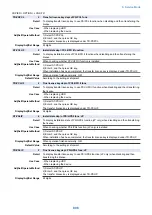

COPIER > OPTION > ACC
MIN-PRC
1
Set of Coin Manager minimum price
Detail
To set the minimum amount to be handled with Coin Manager.
Enter 10 when specifying 10 Japanese yen as the minimum amount to be handled with the Coin
Manager that supports Japanese yen.
In the case to specify 1 to 4 (Euro/Pound/Swiss Franc/Dollar) by going through the following:
COPIER> OPTION> ACC > UNIT-PRC, entry is in fractional unit. Entry of 50 indicates 50 cents
($ 0.50).
Use Case
At installation of Coin Manager
Adj/Set/Operate Method
1) Enter the setting value, and then press OK key.
2) Turn OFF/ON the main power switch.
Caution
This mode is enabled when selecting 4 for the following: COPIER> OPTION> ACC> COIN.
Display/Adj/Set Range
0 to 9999
Default Value
10
Related Service Mode
COPIER> OPTION> ACC> COIN, UNIT-PRC
Supplement/Memo
When a value smaller than the minimum amount is entered in Settings/Registration menu as the
charging amount, it causes an error.
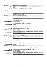
MAX-PRC
1
Set of Coin Manager maximum price
Detail
To set the maximum amount to be handled with Coin Manager.
Enter 8800 when specifying 8800 Japanese yen as the maximum amount to be handled with the
Coin Manager that supports Japanese yen.
Use Case
At installation of Coin Manager
Adj/Set/Operate Method
1) Enter the setting value, and then press OK key.
2) Turn OFF/ON the main power switch.
Caution
This mode is enabled when selecting 4 for the following: COPIER> OPTION> ACC> COIN.
Display/Adj/Set Range
0 to 9999
Default Value
8800
Related Service Mode
COPIER> OPTION> ACC> COIN, UNIT-PRC
Supplement/Memo
When a value larger than the maximum amount is entered in Settings/Registration menu as the
charging amount, it causes an error.
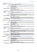
MIC-TUN
1
Manual adj of voice recognize microphone
Detail
To manually adjust the voice receiving level (sensitivity) of the connected voice recognition
microphone.
Microphone sensitivity is automatically tuned in Settings/Registration menu; however, adjust it
manually as needed.
Use Case
When the sensitivity of microphone is not improved by auto tuning
Adj/Set/Operate Method
1) Enter the setting value, and then press OK key.
2) Turn OFF/ON the main power switch.
Display/Adj/Set Range
0 to 255
Default Value
128
Additional Functions
Mode
Preferences> Accessibility> Voice Navigation Settings> Tune Microphone
8. Service Mode
794
Содержание imagerunner advance 4551i
Страница 19: ...Product Overview 1 Product Lineup 7 Features 13 Specifications 16 Name of Parts 26 ...
Страница 155: ...Periodical Service 3 Consumable Parts List 143 Cleaning Check Adjustment Locations 146 ...
Страница 175: ...Switch SW1 SW2 SW4 Symbol Name SW1 Main Switch SW2 Front Door Switch SW4 Environment Switch 4 Disassembly Assembly 162 ...
Страница 244: ...3 Remove the Platen roller unit 1 2 Claws 2 2x 2 1 2 4 Remove the Cover 1 2 Screws 2 2x 2 1 4 Disassembly Assembly 231 ...
Страница 295: ...2 Remove the Multi purpose Tray Pickup Roller Cover 1 1 Screw 2 1x 1 2 4 Disassembly Assembly 282 ...
Страница 392: ...Error Jam Alarm 7 Overview 380 Error Code 383 Jam Code 509 Alarm Code 520 ...
Страница 545: ...Service Mode 8 Overview 533 COPIER 549 FEEDER 845 SORTER 851 BOARD 871 ...
Страница 549: ... i Press the button to display the screen showing the locations of electrical components 8 Service Mode 536 ...
Страница 892: ...Unpacking 1 2 1200 mm 840 mm 769 mm 1230 mm 2430 mm 3 9 Installation 879 ...
Страница 895: ...3 4 NOTE Keep the removed screws for relocating the host machine 2x 5 6 7 9 Installation 882 ...
Страница 896: ...8 9 10 1x Installing the Air Filter 1 9 Installation 883 ...
Страница 897: ...2 3 Installing the Drum Unit 1 2 3 9 Installation 884 ...
Страница 899: ...8 NOTE The screw removed at procedure 4 is used 1x 9 10 11 12 9 Installation 886 ...
Страница 921: ...7 2x 8 2x Binding M4x8 NOTE After completion of the work perform Installing the Equipment 9 Installation 908 ...
Страница 923: ...5 6 NOTE Use the screws and Rubber Caps removed in step 1 2x 7 2x 9 Installation 910 ...
Страница 931: ...5 1x 6 1x 7 1x 1x P Tightening M3x12 8 NOTE Use the part removed in step 3 1x 9 9 Installation 918 ...
Страница 935: ...7 1x 8 9 6x 10 2x 9 Installation 922 ...
Страница 936: ...11 Installing the NFC Kit 1 2 2x 3 TP M3x4 1x 9 Installation 923 ...
Страница 938: ...4 5 1x 6 9 Installation 925 ...
Страница 970: ...38 Close the Front Cover 39 Close the Right Cover 40 Turn the environment Heater Switch ON 9 Installation 957 ...
Страница 985: ...8 2x 2x TP M4x8 Black When installing the USB Keyboard 1 9 Installation 972 ...
Страница 991: ...7 4x 8 1x 1x Lower Cover 9 1x 10 1x 1x 9 Installation 978 ...
Страница 992: ...11 1x 1x 12 1x 13 TP M3x12 2x 14 4x TP M3x6 9 Installation 979 ...
Страница 997: ...Installation Procedure 1 2 2x 3 2x 4 6x 5 4x 9 Installation 984 ...
Страница 998: ...6 7 NOTE Do not close the Wire Saddle 1x 1x 8 9 9 Installation 985 ...
Страница 1000: ...12 NOTE Be sure to adjust the number of cushions according to the thickness of the Card Reader 13 14 15 16 9 Installation 987 ...
Страница 1001: ...17 2x 18 19 Connect the power plug of the host machine to the power outlet 20 Turn the main power switch ON 9 Installation 988 ...
Страница 1003: ...2 1x 1x 3 2x 2x 4 9 Installation 990 ...
Страница 1007: ...13 4x 14 15 2x NOTE The removed screw is used at procedure 17 16 Binding M4x14 Binding M3x14 2x M4x14 M3x14 9 Installation 994 ...
Страница 1008: ...17 NOTE Use the screw removed at procedure 15 2x 18 19 20 NOTE Install both side of the cable 9 Installation 995 ...
Страница 1012: ...2 1x 1x 3 2x 2x 4 9 Installation 999 ...
Страница 1014: ...7 CAUTION The connector must be contacted TP㸹M3x6 3x 1x 8 4x 9 9 Installation 1001 ...
Страница 1016: ...13 4x 14 15 Binding M4x16 Binding M3x16 2x M3x16 M4x16 16 Binding M4x6 1x 9 Installation 1003 ...
Страница 1017: ...17 NOTE Be sure to attach the Ring Cores within 50 mm from the end of the Speaker Cable 50mm 18 2x 19 20 9 Installation 1004 ...
Страница 1023: ...Installation Procedure Preparation 1 4x 2 1x 1x 3 2x 9 Installation 1010 ...
Страница 1026: ...2 4x 3 Connect the power plug of the host machine to the power outlet 4 Turn ON the main power switch 9 Installation 1013 ...
Страница 1029: ...4 5 1x 1x 9 Installation 1016 ...
Страница 1044: ...6 7 8 9 Be sure to request the user to padlock the removable HDD to discourage theft 10 4x 11 9 Installation 1031 ...
Страница 1048: ...3 2x TP M3x8 Black 4 2x TP M3x6 5 9 Installation 1035 ...
Страница 1053: ... Installing the Removable HDD Kit 1 2x 2x 2 3 1x 4 9 Installation 1040 ...
Страница 1065: ...3 2x TP M3x8 Black 4 2x TP M3x6 5 9 Installation 1052 ...
Страница 1071: ... Installing the Removable HDD Kit 1 2x 2x 2 3 1x 4 9 Installation 1058 ...


