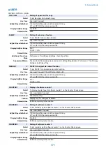


COPIER > OPTION > USER
POL-SCAN
1
Dspl/hide Rights Management Server set
Detail
When "1: Display" is set, the Rights Management Server function screen is displayed.
While the Rights Management Server function is a standard feature, it is possible to hide if not
necessary.
Use Case
Upon user's request
Adj/Set/Operate Method
1) Enter the setting value, and then press OK key.
2) Turn OFF/ON the main power switch.
Display/Adj/Set Range
0 to 1
0: Hide, 1: Display
Default Value
It differs according to the location.
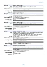
PH-D-SL2
2
Set halftone process in text/photo mode
Detail
When copying or B&W scanning to Inbox in text/photo mode, halftone processing of the image
which reproduces gradation of text and photo judgment areas can be specified with this setting.
Set to 1 when jaggy occurs or request to use the same halftoning method (text area) as
conventional one is raised.
Set to 2 when moire occurs frequently or request to use the same halftoning method as
conventional B&W MFP method is raised.
Even 0 is set, TBIC is used for text judgment area and low screen ruling for photo judgment area
at the time of B&W Inbox scan.
The setting is disabled when the B&W Inbox scanning density is set to auto.
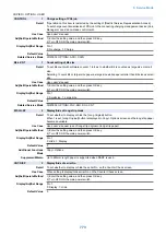
Use Case
- When jaggy occurs on the edge of text or thin lines at copy output. Especially when jaggy occurs
in the text or thin lines (text in halftone dots) of the area where gradation in the halftone density is
expressed like photo, graphics, etc.
- When moire occurs frequently at the time of copy or B&W Inbox scan Especially when moire
frequently occurs in the area where gradation in the halftone density is expressed like photo,
graphics, etc. and this symptom is not alleviated with PH-D-SEL or sharpness adjustment
- When receiving a request to use the same halftoning method (text area) as the conventional one
(model with image area separation method) at copy output
- When receiving a request to use the same halftoning method (both text and photo areas) as the
conventional B&W MFP method at the time of copy or B&W Inbox output
Adj/Set/Operate Method
1) Enter the setting value, and then press OK key.
2) Turn OFF/ON the main power switch.
Display/Adj/Set Range
0 to 2
0: Low screen ruling (134 lines) is used for photo judgment area and high screen ruling (141 lines)
for text judgment area.
1: Low screen ruling is used for photo judgment area and TBIC for text judgment area.
2: TBIC is used for both photo and text judgment areas.
Default Value
0
Related Service Mode
COPIER> OPTION> USER> PH-D-SEL
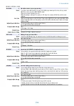
SCAN-RSL
2
Setting of scanned image resolution
Detail
To set the resolution of image which is generated by scan processing.
Use Case
When the scan processing performance with 1200 dpi is low
Adj/Set/Operate Method
1) Enter the setting value, and then press OK key.
2) Turn OFF/ON the main power switch.
Display/Adj/Set Range
0 to 1
0: 600 dpi, 1: 1200 dpi
Default Value
0
8. Service Mode
785
Содержание imagerunner advance 4551i
Страница 19: ...Product Overview 1 Product Lineup 7 Features 13 Specifications 16 Name of Parts 26 ...
Страница 155: ...Periodical Service 3 Consumable Parts List 143 Cleaning Check Adjustment Locations 146 ...
Страница 175: ...Switch SW1 SW2 SW4 Symbol Name SW1 Main Switch SW2 Front Door Switch SW4 Environment Switch 4 Disassembly Assembly 162 ...
Страница 244: ...3 Remove the Platen roller unit 1 2 Claws 2 2x 2 1 2 4 Remove the Cover 1 2 Screws 2 2x 2 1 4 Disassembly Assembly 231 ...
Страница 295: ...2 Remove the Multi purpose Tray Pickup Roller Cover 1 1 Screw 2 1x 1 2 4 Disassembly Assembly 282 ...
Страница 392: ...Error Jam Alarm 7 Overview 380 Error Code 383 Jam Code 509 Alarm Code 520 ...
Страница 545: ...Service Mode 8 Overview 533 COPIER 549 FEEDER 845 SORTER 851 BOARD 871 ...
Страница 549: ... i Press the button to display the screen showing the locations of electrical components 8 Service Mode 536 ...
Страница 892: ...Unpacking 1 2 1200 mm 840 mm 769 mm 1230 mm 2430 mm 3 9 Installation 879 ...
Страница 895: ...3 4 NOTE Keep the removed screws for relocating the host machine 2x 5 6 7 9 Installation 882 ...
Страница 896: ...8 9 10 1x Installing the Air Filter 1 9 Installation 883 ...
Страница 897: ...2 3 Installing the Drum Unit 1 2 3 9 Installation 884 ...
Страница 899: ...8 NOTE The screw removed at procedure 4 is used 1x 9 10 11 12 9 Installation 886 ...
Страница 921: ...7 2x 8 2x Binding M4x8 NOTE After completion of the work perform Installing the Equipment 9 Installation 908 ...
Страница 923: ...5 6 NOTE Use the screws and Rubber Caps removed in step 1 2x 7 2x 9 Installation 910 ...
Страница 931: ...5 1x 6 1x 7 1x 1x P Tightening M3x12 8 NOTE Use the part removed in step 3 1x 9 9 Installation 918 ...
Страница 935: ...7 1x 8 9 6x 10 2x 9 Installation 922 ...
Страница 936: ...11 Installing the NFC Kit 1 2 2x 3 TP M3x4 1x 9 Installation 923 ...
Страница 938: ...4 5 1x 6 9 Installation 925 ...
Страница 970: ...38 Close the Front Cover 39 Close the Right Cover 40 Turn the environment Heater Switch ON 9 Installation 957 ...
Страница 985: ...8 2x 2x TP M4x8 Black When installing the USB Keyboard 1 9 Installation 972 ...
Страница 991: ...7 4x 8 1x 1x Lower Cover 9 1x 10 1x 1x 9 Installation 978 ...
Страница 992: ...11 1x 1x 12 1x 13 TP M3x12 2x 14 4x TP M3x6 9 Installation 979 ...
Страница 997: ...Installation Procedure 1 2 2x 3 2x 4 6x 5 4x 9 Installation 984 ...
Страница 998: ...6 7 NOTE Do not close the Wire Saddle 1x 1x 8 9 9 Installation 985 ...
Страница 1000: ...12 NOTE Be sure to adjust the number of cushions according to the thickness of the Card Reader 13 14 15 16 9 Installation 987 ...
Страница 1001: ...17 2x 18 19 Connect the power plug of the host machine to the power outlet 20 Turn the main power switch ON 9 Installation 988 ...
Страница 1003: ...2 1x 1x 3 2x 2x 4 9 Installation 990 ...
Страница 1007: ...13 4x 14 15 2x NOTE The removed screw is used at procedure 17 16 Binding M4x14 Binding M3x14 2x M4x14 M3x14 9 Installation 994 ...
Страница 1008: ...17 NOTE Use the screw removed at procedure 15 2x 18 19 20 NOTE Install both side of the cable 9 Installation 995 ...
Страница 1012: ...2 1x 1x 3 2x 2x 4 9 Installation 999 ...
Страница 1014: ...7 CAUTION The connector must be contacted TP㸹M3x6 3x 1x 8 4x 9 9 Installation 1001 ...
Страница 1016: ...13 4x 14 15 Binding M4x16 Binding M3x16 2x M3x16 M4x16 16 Binding M4x6 1x 9 Installation 1003 ...
Страница 1017: ...17 NOTE Be sure to attach the Ring Cores within 50 mm from the end of the Speaker Cable 50mm 18 2x 19 20 9 Installation 1004 ...
Страница 1023: ...Installation Procedure Preparation 1 4x 2 1x 1x 3 2x 9 Installation 1010 ...
Страница 1026: ...2 4x 3 Connect the power plug of the host machine to the power outlet 4 Turn ON the main power switch 9 Installation 1013 ...
Страница 1029: ...4 5 1x 1x 9 Installation 1016 ...
Страница 1044: ...6 7 8 9 Be sure to request the user to padlock the removable HDD to discourage theft 10 4x 11 9 Installation 1031 ...
Страница 1048: ...3 2x TP M3x8 Black 4 2x TP M3x6 5 9 Installation 1035 ...
Страница 1053: ... Installing the Removable HDD Kit 1 2x 2x 2 3 1x 4 9 Installation 1040 ...
Страница 1065: ...3 2x TP M3x8 Black 4 2x TP M3x6 5 9 Installation 1052 ...
Страница 1071: ... Installing the Removable HDD Kit 1 2x 2x 2 3 1x 4 9 Installation 1058 ...


