


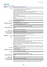


COPIER > OPTION > NETWORK
IPTBROAD
1
Set to allow broad/multicast TX
Detail
*Operation on this item is restricted by the setting of [Restrict Service Representation Access].
To set whether to permit transmission of broadcast packets and multicast packets.
Transmission of broadcast packets and multicast packets is permitted without specifying an
exception address. It is permitted within the device even if it is rejected in the default setting of the
IPv4/v6 transmission filter.
Set "1: Disabled" when the user does not want to send them.
Use Case
Upon user's request
Adj/Set/Operate Method
Enter the setting value, and then press OK key.
Display/Adj/Set Range
0 to 5
0: Enabled, 1: Disabled, 2 to 5: Not used
Default Value
0
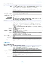
PFWFTPRT
1
Set of RST reply at IP filter FTP SEND
Detail
*Operation on this item is restricted by the setting of [Restrict Service Representation Access].
When FTP SEND is executed using an IP filter by which packets from a specific remote PC are
rejected, SYN is returned to the port 113 if the PC supports authentication of the FTP port 113.
However, since the IP filter blocks the packets, the block logs are increased and the performance
is lowered.
When 1 is set, RST is returned to the port 113 without blocking packets.
Use Case
When executing FTP SEND against the OS which supports authentication of the FTP port 113
while the IP filter is enabled
Adj/Set/Operate Method
Enter the setting value, and then press OK key.
Display/Adj/Set Range
0 to 1
0: OFF, 1: ON
Default Value
0
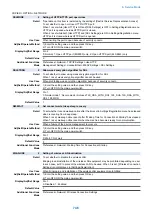
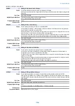
IPMTU
1
Setting of MTU size
Detail
To set MTU size of network packet.
This item is used when performing SEND communication between locations connected with
Ethernet in a field environment where MTU black hole problem occurs.
Use Case
When MTU black hole problem occur
Adj/Set/Operate Method
Enter the setting value, and then press OK key.
Caution
With IPv6, use of MTU which size is less than 1280 bytes is not recommended by RFC.
Therefore, when setting IPv6 to ON and MTU to 7 or smaller, communication using IPv6 may not
be available.
Display/Adj/Set Range
1 to 10
1: 600 byte, 2: 700 byte, ..., 9: 1400 byte, 10: 1500 byte
Unit
byte
Default Value
10
Supplement/Memo
MTU: The maximum size of data unit that can be transmitted with a single transfer (1 frame) over
network.
MTU black hole: A problem which occurs when ICMP packets are filtered by firewall, etc. (Since
no message is sent to the sender, the sender does not notice that the packets are discarded and
timeout occurs.)
Amount of Change per
Unit
100
8. Service Mode
743
Содержание imagerunner advance 4551i
Страница 19: ...Product Overview 1 Product Lineup 7 Features 13 Specifications 16 Name of Parts 26 ...
Страница 155: ...Periodical Service 3 Consumable Parts List 143 Cleaning Check Adjustment Locations 146 ...
Страница 175: ...Switch SW1 SW2 SW4 Symbol Name SW1 Main Switch SW2 Front Door Switch SW4 Environment Switch 4 Disassembly Assembly 162 ...
Страница 244: ...3 Remove the Platen roller unit 1 2 Claws 2 2x 2 1 2 4 Remove the Cover 1 2 Screws 2 2x 2 1 4 Disassembly Assembly 231 ...
Страница 295: ...2 Remove the Multi purpose Tray Pickup Roller Cover 1 1 Screw 2 1x 1 2 4 Disassembly Assembly 282 ...
Страница 392: ...Error Jam Alarm 7 Overview 380 Error Code 383 Jam Code 509 Alarm Code 520 ...
Страница 545: ...Service Mode 8 Overview 533 COPIER 549 FEEDER 845 SORTER 851 BOARD 871 ...
Страница 549: ... i Press the button to display the screen showing the locations of electrical components 8 Service Mode 536 ...
Страница 892: ...Unpacking 1 2 1200 mm 840 mm 769 mm 1230 mm 2430 mm 3 9 Installation 879 ...
Страница 895: ...3 4 NOTE Keep the removed screws for relocating the host machine 2x 5 6 7 9 Installation 882 ...
Страница 896: ...8 9 10 1x Installing the Air Filter 1 9 Installation 883 ...
Страница 897: ...2 3 Installing the Drum Unit 1 2 3 9 Installation 884 ...
Страница 899: ...8 NOTE The screw removed at procedure 4 is used 1x 9 10 11 12 9 Installation 886 ...
Страница 921: ...7 2x 8 2x Binding M4x8 NOTE After completion of the work perform Installing the Equipment 9 Installation 908 ...
Страница 923: ...5 6 NOTE Use the screws and Rubber Caps removed in step 1 2x 7 2x 9 Installation 910 ...
Страница 931: ...5 1x 6 1x 7 1x 1x P Tightening M3x12 8 NOTE Use the part removed in step 3 1x 9 9 Installation 918 ...
Страница 935: ...7 1x 8 9 6x 10 2x 9 Installation 922 ...
Страница 936: ...11 Installing the NFC Kit 1 2 2x 3 TP M3x4 1x 9 Installation 923 ...
Страница 938: ...4 5 1x 6 9 Installation 925 ...
Страница 970: ...38 Close the Front Cover 39 Close the Right Cover 40 Turn the environment Heater Switch ON 9 Installation 957 ...
Страница 985: ...8 2x 2x TP M4x8 Black When installing the USB Keyboard 1 9 Installation 972 ...
Страница 991: ...7 4x 8 1x 1x Lower Cover 9 1x 10 1x 1x 9 Installation 978 ...
Страница 992: ...11 1x 1x 12 1x 13 TP M3x12 2x 14 4x TP M3x6 9 Installation 979 ...
Страница 997: ...Installation Procedure 1 2 2x 3 2x 4 6x 5 4x 9 Installation 984 ...
Страница 998: ...6 7 NOTE Do not close the Wire Saddle 1x 1x 8 9 9 Installation 985 ...
Страница 1000: ...12 NOTE Be sure to adjust the number of cushions according to the thickness of the Card Reader 13 14 15 16 9 Installation 987 ...
Страница 1001: ...17 2x 18 19 Connect the power plug of the host machine to the power outlet 20 Turn the main power switch ON 9 Installation 988 ...
Страница 1003: ...2 1x 1x 3 2x 2x 4 9 Installation 990 ...
Страница 1007: ...13 4x 14 15 2x NOTE The removed screw is used at procedure 17 16 Binding M4x14 Binding M3x14 2x M4x14 M3x14 9 Installation 994 ...
Страница 1008: ...17 NOTE Use the screw removed at procedure 15 2x 18 19 20 NOTE Install both side of the cable 9 Installation 995 ...
Страница 1012: ...2 1x 1x 3 2x 2x 4 9 Installation 999 ...
Страница 1014: ...7 CAUTION The connector must be contacted TP㸹M3x6 3x 1x 8 4x 9 9 Installation 1001 ...
Страница 1016: ...13 4x 14 15 Binding M4x16 Binding M3x16 2x M3x16 M4x16 16 Binding M4x6 1x 9 Installation 1003 ...
Страница 1017: ...17 NOTE Be sure to attach the Ring Cores within 50 mm from the end of the Speaker Cable 50mm 18 2x 19 20 9 Installation 1004 ...
Страница 1023: ...Installation Procedure Preparation 1 4x 2 1x 1x 3 2x 9 Installation 1010 ...
Страница 1026: ...2 4x 3 Connect the power plug of the host machine to the power outlet 4 Turn ON the main power switch 9 Installation 1013 ...
Страница 1029: ...4 5 1x 1x 9 Installation 1016 ...
Страница 1044: ...6 7 8 9 Be sure to request the user to padlock the removable HDD to discourage theft 10 4x 11 9 Installation 1031 ...
Страница 1048: ...3 2x TP M3x8 Black 4 2x TP M3x6 5 9 Installation 1035 ...
Страница 1053: ... Installing the Removable HDD Kit 1 2x 2x 2 3 1x 4 9 Installation 1040 ...
Страница 1065: ...3 2x TP M3x8 Black 4 2x TP M3x6 5 9 Installation 1052 ...
Страница 1071: ... Installing the Removable HDD Kit 1 2x 2x 2 3 1x 4 9 Installation 1058 ...


