
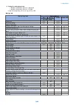


Backup target data
Backup Method
User
Service
DCM
Power OFF
(excluding DCM)
Key Pair and Server Certificate in Certificate Settings in TCP/IP Settings in
Network Set-tings in System Settings (from the Additional Functions
screen)
-
-
Yes*9
-
Auto Adjust Gradation setting values
-
-
-
-
PS font
-
-
-
-
Key information to be used for encryption when TPM is OFF
-
-
-
-
Key and settings information to be used for encryption when TPM is ON
Yes*7
-
-
-
Personal Settings
Display Language
-
-
Yes *9
-
Accessibility Settings
-
-
Yes *9
-
Default Screen
-
-
Yes *9
-
Default Job Settings
-
-
Yes *9
-
Quick Menu (Personal, layout of the Personal tab, and background of the
Personal tab)
-
-
Yes *9
-
Address Book (Personal/Group)
Yes *1
-
Yes *9
-
Key ring (for host machine functions)
-
-
Yes *9
-
Personal settings of MEAP
Yes *11
Yes *8
Yes *9
-
Service Mode
Service Mode setting values (MN-CON)
-
-
Yes*9
Yes*10
*1: Remote UI > Settings/Registration > Management Settings > Data Management > Import or Export
*2: Remote UI > Settings/Registration > Management Settings > User Management > Authentication Management > User
Management
*3: Remote UI > Quick Menu > Export
*4: Remote UI > Settings/Registration > Management Settings > Data Management > Back Up or Restore
*5: Remote UI > Service Management Service
*6: Remote UI > Settings/Registration > Management Settings > Device Management > Save Audit Log
Audit log that was exported cannot be put back to the device from which the log was exported.
*7: Settings/Registration > Management Settings > Data Management > TPM Settings
*8: Download mode > [5]: Backup/Restore > [3] : MEAP Backup > Meapback.bin Backup is possible using SST or USB memory
The data saved using a MEAP application can be backed up only when the MEAP application has a backup function.
*9: Backup Method using DCM When You set it in COPIER> OPTION> USER> SMD-EXPT> ON, a backup/restore is possible
in Service Mode Settings from the Remote UI.There is a backup button on the TOP page of the service mode.
1. Remote UI > Settings/Registration > Management Settings > Data Management > Import/Export All
2. Remote UI > Settings/Registration > Management Settings > Data Management > Import/Export
3. Service mode top screen > BACKUP
4. Web Service
*10: The setting value that was set when the main power was turned OFF the last time is automatically backed up to the Flash
PCB. When a HDD is replaced with a new one, the setting value is automatically inherited from the Flash PCB at the time of HDD
formatting.
*11: iWEMC DAM plug-in
■ Aftter Replacement
1. HDD format
Start the machine in safe mode, and format all partitions using SST or a USB memory.
2. Turning OFF and ON the main power switch.
3. Restore the backup data.
4. Execute reset/register the data referring the printed list before the replacement.
5. When the user already generates and adds the encryption key, certificate and/or CA certificate, ask the user to
generate them again.
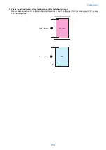
6. Execute auto gradation adjustment.
• Settings/Registration > Adjustment/Maintenance > Adjust Image Quality > Auto Adjust Gradation > Full Adjust
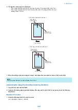
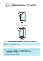
5. Adjustment
327
Содержание imagerunner advance 4551i
Страница 19: ...Product Overview 1 Product Lineup 7 Features 13 Specifications 16 Name of Parts 26 ...
Страница 155: ...Periodical Service 3 Consumable Parts List 143 Cleaning Check Adjustment Locations 146 ...
Страница 175: ...Switch SW1 SW2 SW4 Symbol Name SW1 Main Switch SW2 Front Door Switch SW4 Environment Switch 4 Disassembly Assembly 162 ...
Страница 244: ...3 Remove the Platen roller unit 1 2 Claws 2 2x 2 1 2 4 Remove the Cover 1 2 Screws 2 2x 2 1 4 Disassembly Assembly 231 ...
Страница 295: ...2 Remove the Multi purpose Tray Pickup Roller Cover 1 1 Screw 2 1x 1 2 4 Disassembly Assembly 282 ...
Страница 392: ...Error Jam Alarm 7 Overview 380 Error Code 383 Jam Code 509 Alarm Code 520 ...
Страница 545: ...Service Mode 8 Overview 533 COPIER 549 FEEDER 845 SORTER 851 BOARD 871 ...
Страница 549: ... i Press the button to display the screen showing the locations of electrical components 8 Service Mode 536 ...
Страница 892: ...Unpacking 1 2 1200 mm 840 mm 769 mm 1230 mm 2430 mm 3 9 Installation 879 ...
Страница 895: ...3 4 NOTE Keep the removed screws for relocating the host machine 2x 5 6 7 9 Installation 882 ...
Страница 896: ...8 9 10 1x Installing the Air Filter 1 9 Installation 883 ...
Страница 897: ...2 3 Installing the Drum Unit 1 2 3 9 Installation 884 ...
Страница 899: ...8 NOTE The screw removed at procedure 4 is used 1x 9 10 11 12 9 Installation 886 ...
Страница 921: ...7 2x 8 2x Binding M4x8 NOTE After completion of the work perform Installing the Equipment 9 Installation 908 ...
Страница 923: ...5 6 NOTE Use the screws and Rubber Caps removed in step 1 2x 7 2x 9 Installation 910 ...
Страница 931: ...5 1x 6 1x 7 1x 1x P Tightening M3x12 8 NOTE Use the part removed in step 3 1x 9 9 Installation 918 ...
Страница 935: ...7 1x 8 9 6x 10 2x 9 Installation 922 ...
Страница 936: ...11 Installing the NFC Kit 1 2 2x 3 TP M3x4 1x 9 Installation 923 ...
Страница 938: ...4 5 1x 6 9 Installation 925 ...
Страница 970: ...38 Close the Front Cover 39 Close the Right Cover 40 Turn the environment Heater Switch ON 9 Installation 957 ...
Страница 985: ...8 2x 2x TP M4x8 Black When installing the USB Keyboard 1 9 Installation 972 ...
Страница 991: ...7 4x 8 1x 1x Lower Cover 9 1x 10 1x 1x 9 Installation 978 ...
Страница 992: ...11 1x 1x 12 1x 13 TP M3x12 2x 14 4x TP M3x6 9 Installation 979 ...
Страница 997: ...Installation Procedure 1 2 2x 3 2x 4 6x 5 4x 9 Installation 984 ...
Страница 998: ...6 7 NOTE Do not close the Wire Saddle 1x 1x 8 9 9 Installation 985 ...
Страница 1000: ...12 NOTE Be sure to adjust the number of cushions according to the thickness of the Card Reader 13 14 15 16 9 Installation 987 ...
Страница 1001: ...17 2x 18 19 Connect the power plug of the host machine to the power outlet 20 Turn the main power switch ON 9 Installation 988 ...
Страница 1003: ...2 1x 1x 3 2x 2x 4 9 Installation 990 ...
Страница 1007: ...13 4x 14 15 2x NOTE The removed screw is used at procedure 17 16 Binding M4x14 Binding M3x14 2x M4x14 M3x14 9 Installation 994 ...
Страница 1008: ...17 NOTE Use the screw removed at procedure 15 2x 18 19 20 NOTE Install both side of the cable 9 Installation 995 ...
Страница 1012: ...2 1x 1x 3 2x 2x 4 9 Installation 999 ...
Страница 1014: ...7 CAUTION The connector must be contacted TP㸹M3x6 3x 1x 8 4x 9 9 Installation 1001 ...
Страница 1016: ...13 4x 14 15 Binding M4x16 Binding M3x16 2x M3x16 M4x16 16 Binding M4x6 1x 9 Installation 1003 ...
Страница 1017: ...17 NOTE Be sure to attach the Ring Cores within 50 mm from the end of the Speaker Cable 50mm 18 2x 19 20 9 Installation 1004 ...
Страница 1023: ...Installation Procedure Preparation 1 4x 2 1x 1x 3 2x 9 Installation 1010 ...
Страница 1026: ...2 4x 3 Connect the power plug of the host machine to the power outlet 4 Turn ON the main power switch 9 Installation 1013 ...
Страница 1029: ...4 5 1x 1x 9 Installation 1016 ...
Страница 1044: ...6 7 8 9 Be sure to request the user to padlock the removable HDD to discourage theft 10 4x 11 9 Installation 1031 ...
Страница 1048: ...3 2x TP M3x8 Black 4 2x TP M3x6 5 9 Installation 1035 ...
Страница 1053: ... Installing the Removable HDD Kit 1 2x 2x 2 3 1x 4 9 Installation 1040 ...
Страница 1065: ...3 2x TP M3x8 Black 4 2x TP M3x6 5 9 Installation 1052 ...
Страница 1071: ... Installing the Removable HDD Kit 1 2x 2x 2 3 1x 4 9 Installation 1058 ...


