


Host machine_3/18
A
C
B
D
E
F
A
C
B
D
E
F
4
3
2
7
6
5
1
8
4
3
2
7
6
5
1
8
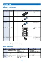
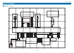
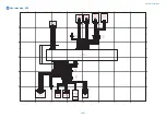
Right Cover Unit
Main Drive Unit
First Delivery Unit
Second Delivery Unit
EXIT
2
_
P_
SNS
G
N
D
EXI
T
2_F
U
LL_SN
S
G
N
D
+2
4
V
+5
V_
D
C
O
N
EXIT
2
_
SL
_
ON
+5
V_
D
C
O
N
EXI
T
_
M_
BN
G
N
D
R
VR
S_
P_
SN
S
R
V
R
S
_
M
_
B
N
R
VR
S_
M_
B
R
V
R
S
_
M
_
A
N
R
VR
S_
M_
A
+5
V_
D
C
O
N
EXIT
1
_
P_
SNS
EXI
T
1_F
U
LL_SN
S
G
N
D
+5
V_
D
C
O
N
EXI
T
_
M_
AN
EXI
T_
M_
B
EXI
T_
M_
A
G
N
D
+5
V_
D
C
O
N
MAI
N
_
M_
F
G
+2
4
V_
L
O
C
K
N
.C
.
R
EG
I_
C
L
_
O
N
+2
4
V
+2
4
V_
L
O
C
K
G
N
D
MAIN
_
M_
AC
C
G
N
D
MAIN
_
M_
D
EC
MU
L
T
_
C
L
_
O
N
+2
4
V
+2
4
V
SL
EEV_
CL
_
ON
D
U
P_M_A
D
U
P_
M_
AN
D
U
P_M_B
D
U
P_
M_
BN
L
O
O
P_
SN
S
+5
V_
D
C
O
N
G
N
D
G
N
D
MP_
SI
Z
E_
SN
S
+3
.3
V_
D
C
O
N
D
U
P_
P_
SN
S
G
N
D
+5
V_
D
C
O
N
W
AST
_
F
AN
_
R
_
O
N
W
AST
_
F
AN
_
F
_
L
O
C
K
G
N
D
W
AST
_
F
AN
_
F
_
O
N
R
EVER
SE_
SL
_
O
N
+2
4
V_
D
C
O
N
_
SL
C
L
1
MU
L
T
_
SL
_
O
N
+2
4
V_
D
C
O
N
_
SL
C
L
1
+5
V_
SESA
W
_
C
N
T
G
N
D
MP_
P_
SN
S
MP_
P_
EX1
_
SN
S
G
N
D
+5
V_
D
C
O
N
P_
C
O
O
L
_
F
AN
_
L
O
C
K
G
N
D
P_
C
O
O
L
_
F
AN
_
O
N
W
AST
_
F
AN
_
R
_
L
O
C
K
G
N
D
1
2
3
J5
3 2 1
1
2
J2060D1
J2060DH1
1 2
SL
1 2
1
2
3
3 2 1
3 2 1
J125
1
2
3
J126
1
2
3
4
M
1
2
3
4
1
2
3
4
J127
1
2
3
4
M
3 2 1
1
2
3
J128
1
2
3
J129
3 2 1
7 6 5
3 2 1
4
M
J130
2
1
CL
1 2
1 2
2
1
CL
1 2
2
1
CL
1
2
3
4
M
J2561D1
J2561L1
J2561DH1
1
2
3
4
5
1 2 3 4 5
15
14
13
12
11
10
9
8
2 3 4 5 6
1
7
J2511L
10
9
8
2 3 4 5 6
1
7
J2155L
1 2 3 4 5 6 7
13121110 9 8
2
3
4
5
6
1
7
13
12
11
10
9
8
2 3 4 5 6
1
7
1
2
J137
J2255DH
J2255L
1
2
J2027D
J2027DH
J2028D
J2028DH
1
2
J2075D
J2075DH
1
2
3
4
J737
151413121110 9 8
2
3
4
5
6
1
7
J2511D
J2511DH
15
14
13
12
11
10
9
8
2 3 4 5 6
1
7
10 9 8
2
3
4
5
6
1
7
10
9
8
2 3 4 5 6
1
7
J2155D
J2155DH
1 2 3 4 5 6 7 8
J2255D
1 2 3 4 5 6
1 2 3 4
J312
J332
1 2 3 4 5 6 7 8 9 1011121314151617181920212223242526272829
J335
J309
J328
J311
1
2
3
4
5
6
7
8
9
10
11
12
13
14
15
16
17
18
19
20
21
22
23
24
25
26
27
28
29
J2501D
1 2 3 4 5 6 7 8 9 1011121314151617181920212223242526272829
J2501L
J2501DH
3 2 1
1
2
3
J2506DH
1
2
3
J2506D
1 2 3
J2506L
J2507
1
2
3
J2671D
1 2 3
J2671L
J2671DH
1
2
3
4
J2672D
J2672DH
1 2 3 4
J2672L
1 2 3 4 5
J2571L
1
2
3
4
5
J2571D
J2571DH
1 2
J2059L
1
2
J2059D
J2059DH
3
2
1
1 2 3
1 2 3
3
2
1
1
2
3
J2009D
J2009DH
1
2
3
J2010DH
J2010D
3
2
1
1 2 3
1
2
3
J2209D
J2209DH
3 2 1
1
2
3
J2004
1
2
3
J2006
3 2 1
1
2
3
J741
J2008DH
1
2
J2008D
1 2
SL
1 2
1
2
3
J2007
3 2 1
J2080DH
1 2
SL
1 2 3
1
2
3
J2080D
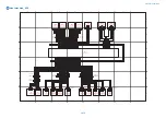
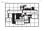
S6
Loop Sensor
S7
Duplex Feed
Sensor
S27
Multi-Purpose Tray
Paper Size Sensor
S50
Multi-Purpose Tray
Paper Length Sensor
S9
Multi-Purpose Tray
Paper Sensor
SL2
Multi-Purpose Tray
Pickup Solenoid
SL12
Reversal
Solenoid
M9
Duplex Feed
Motor
CL12
Multi-Purpose Tray
Pickup Clutch
CL1
Developing
Clutch
CL3
Registration
Clutch
M1
Main Motor
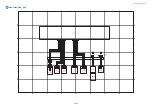
S21
No.1
Delivery
Sensor
S20
No.1
Delivery
Full Sensor
M10
No.1
Delivery
Motor
M20
Reversal
Motor
S24
Reversal
Sensor
S23
No.2
Delivery
Full Sensor
SL13
No.2
Delivery
Solenoid
S22
No.2
Delivery
Sensor
FM4
Heat Exhaust
Fan (Front)
FM3
Heat Exhaust
Fan (Rear)
FM7
Delivery
Cooling Fan
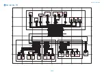
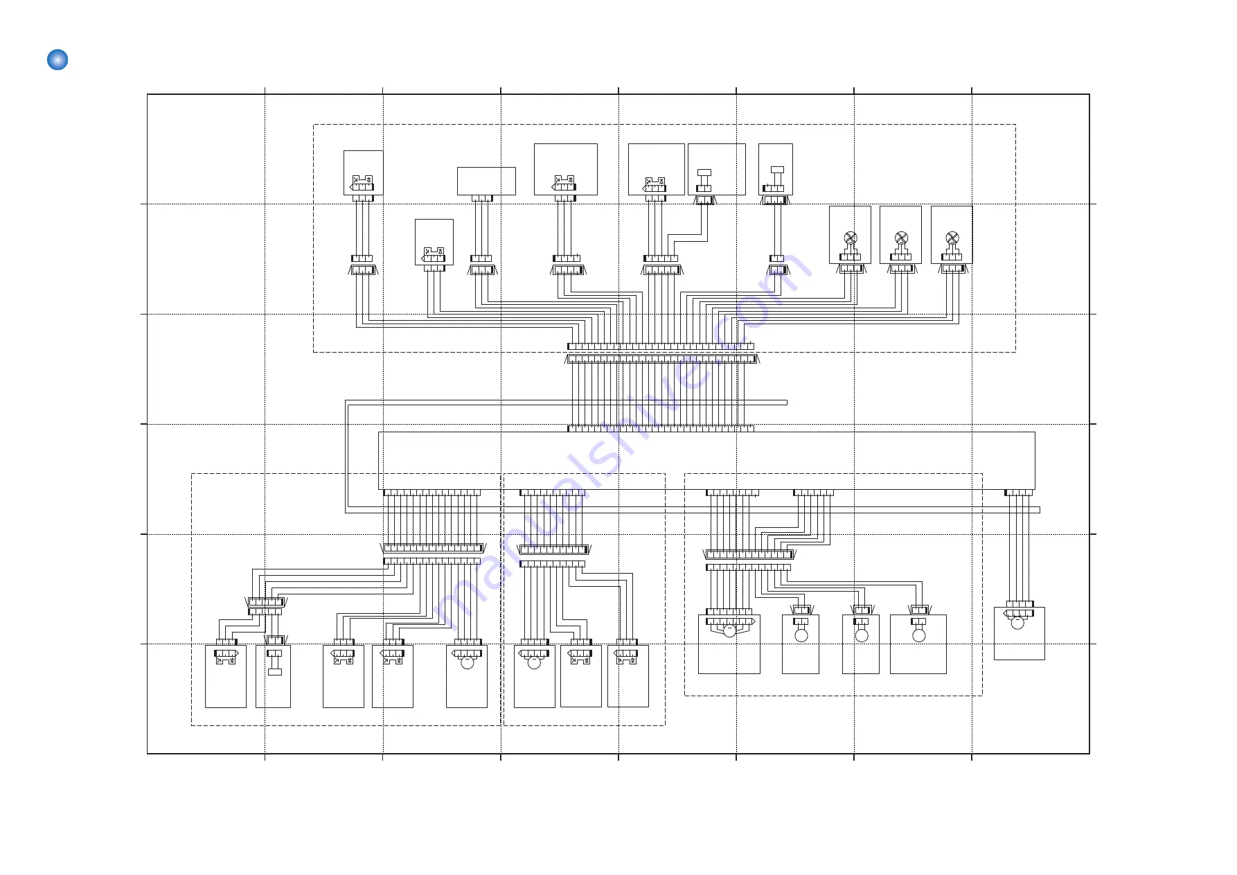
UN2
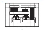
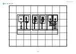
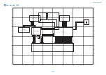
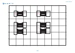
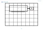
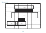
DC Controller PCB
General Circuit Diagram
1074
Содержание imagerunner advance 4551i
Страница 19: ...Product Overview 1 Product Lineup 7 Features 13 Specifications 16 Name of Parts 26 ...
Страница 155: ...Periodical Service 3 Consumable Parts List 143 Cleaning Check Adjustment Locations 146 ...
Страница 175: ...Switch SW1 SW2 SW4 Symbol Name SW1 Main Switch SW2 Front Door Switch SW4 Environment Switch 4 Disassembly Assembly 162 ...
Страница 244: ...3 Remove the Platen roller unit 1 2 Claws 2 2x 2 1 2 4 Remove the Cover 1 2 Screws 2 2x 2 1 4 Disassembly Assembly 231 ...
Страница 295: ...2 Remove the Multi purpose Tray Pickup Roller Cover 1 1 Screw 2 1x 1 2 4 Disassembly Assembly 282 ...
Страница 392: ...Error Jam Alarm 7 Overview 380 Error Code 383 Jam Code 509 Alarm Code 520 ...
Страница 545: ...Service Mode 8 Overview 533 COPIER 549 FEEDER 845 SORTER 851 BOARD 871 ...
Страница 549: ... i Press the button to display the screen showing the locations of electrical components 8 Service Mode 536 ...
Страница 892: ...Unpacking 1 2 1200 mm 840 mm 769 mm 1230 mm 2430 mm 3 9 Installation 879 ...
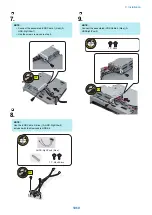
Страница 895: ...3 4 NOTE Keep the removed screws for relocating the host machine 2x 5 6 7 9 Installation 882 ...
Страница 896: ...8 9 10 1x Installing the Air Filter 1 9 Installation 883 ...
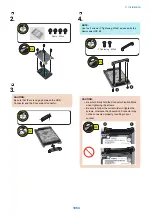
Страница 897: ...2 3 Installing the Drum Unit 1 2 3 9 Installation 884 ...
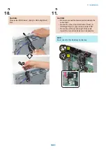
Страница 899: ...8 NOTE The screw removed at procedure 4 is used 1x 9 10 11 12 9 Installation 886 ...
Страница 921: ...7 2x 8 2x Binding M4x8 NOTE After completion of the work perform Installing the Equipment 9 Installation 908 ...
Страница 923: ...5 6 NOTE Use the screws and Rubber Caps removed in step 1 2x 7 2x 9 Installation 910 ...
Страница 931: ...5 1x 6 1x 7 1x 1x P Tightening M3x12 8 NOTE Use the part removed in step 3 1x 9 9 Installation 918 ...
Страница 935: ...7 1x 8 9 6x 10 2x 9 Installation 922 ...
Страница 936: ...11 Installing the NFC Kit 1 2 2x 3 TP M3x4 1x 9 Installation 923 ...
Страница 938: ...4 5 1x 6 9 Installation 925 ...
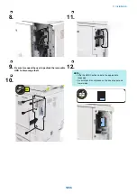
Страница 970: ...38 Close the Front Cover 39 Close the Right Cover 40 Turn the environment Heater Switch ON 9 Installation 957 ...
Страница 985: ...8 2x 2x TP M4x8 Black When installing the USB Keyboard 1 9 Installation 972 ...
Страница 991: ...7 4x 8 1x 1x Lower Cover 9 1x 10 1x 1x 9 Installation 978 ...
Страница 992: ...11 1x 1x 12 1x 13 TP M3x12 2x 14 4x TP M3x6 9 Installation 979 ...
Страница 997: ...Installation Procedure 1 2 2x 3 2x 4 6x 5 4x 9 Installation 984 ...
Страница 998: ...6 7 NOTE Do not close the Wire Saddle 1x 1x 8 9 9 Installation 985 ...
Страница 1000: ...12 NOTE Be sure to adjust the number of cushions according to the thickness of the Card Reader 13 14 15 16 9 Installation 987 ...
Страница 1001: ...17 2x 18 19 Connect the power plug of the host machine to the power outlet 20 Turn the main power switch ON 9 Installation 988 ...
Страница 1003: ...2 1x 1x 3 2x 2x 4 9 Installation 990 ...
Страница 1007: ...13 4x 14 15 2x NOTE The removed screw is used at procedure 17 16 Binding M4x14 Binding M3x14 2x M4x14 M3x14 9 Installation 994 ...
Страница 1008: ...17 NOTE Use the screw removed at procedure 15 2x 18 19 20 NOTE Install both side of the cable 9 Installation 995 ...
Страница 1012: ...2 1x 1x 3 2x 2x 4 9 Installation 999 ...
Страница 1014: ...7 CAUTION The connector must be contacted TP㸹M3x6 3x 1x 8 4x 9 9 Installation 1001 ...
Страница 1016: ...13 4x 14 15 Binding M4x16 Binding M3x16 2x M3x16 M4x16 16 Binding M4x6 1x 9 Installation 1003 ...
Страница 1017: ...17 NOTE Be sure to attach the Ring Cores within 50 mm from the end of the Speaker Cable 50mm 18 2x 19 20 9 Installation 1004 ...
Страница 1023: ...Installation Procedure Preparation 1 4x 2 1x 1x 3 2x 9 Installation 1010 ...
Страница 1026: ...2 4x 3 Connect the power plug of the host machine to the power outlet 4 Turn ON the main power switch 9 Installation 1013 ...
Страница 1029: ...4 5 1x 1x 9 Installation 1016 ...
Страница 1044: ...6 7 8 9 Be sure to request the user to padlock the removable HDD to discourage theft 10 4x 11 9 Installation 1031 ...
Страница 1048: ...3 2x TP M3x8 Black 4 2x TP M3x6 5 9 Installation 1035 ...
Страница 1053: ... Installing the Removable HDD Kit 1 2x 2x 2 3 1x 4 9 Installation 1040 ...
Страница 1065: ...3 2x TP M3x8 Black 4 2x TP M3x6 5 9 Installation 1052 ...
Страница 1071: ... Installing the Removable HDD Kit 1 2x 2x 2 3 1x 4 9 Installation 1058 ...


