


CHAPTER 8 FIXING SYSTEM
8-18
COPYRIGHT © 1999 CANON INC.
CANON GP605/605V REV.0 JAN. 1999 PRINTED IN JAPAN (IMPRIME AU JAPON)
D.
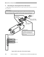
Error Detection
The fixing temperature control mechanism is monitored for the following:
[1] Temperature control error by the main thermistor (TH1; see the sequence charts on the
pages that follow)
[2] Sensor error by the sub thermistor (TH2; see the sequence charts on the pages that follow)
[3] Overheating error by the thermal switch (TP1)
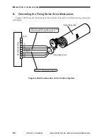
Figure 8-305 Construction of the Control System
DC controller PCB
J508B
1
7
8
10
20
S-TEMP
0V
0V
M-TEMP
Upper fixing roller
Main
heater
Sub thermistor
Main thermistor
Thermal switch
9
J505A
11
10
0V
24V
MHDTC
SHDTC
SH-ON
14
J512A
1
14
13
24V
SW-OFF
RLY
Relay
Front door
SSR
Main switch
12
13
Sub heater
MH-ON
9
1
Voltage suited to the
temperature detected by the
main thermistor
Voltage suited to the
temperature detected by
the sub thermistor
At 223˚C, the AC
line is turned off
When '1', the main heater turns on.
When the sub heater is powered, '0'.
When '0', the main switch is turned off.
Содержание GP605
Страница 3: ......
Страница 4: ......
Страница 24: ......
Страница 56: ......
Страница 78: ......
Страница 116: ......
Страница 124: ......
Страница 148: ......
Страница 150: ......
Страница 168: ......
Страница 170: ......
Страница 250: ......
Страница 252: ......
Страница 342: ......
Страница 390: ......
Страница 392: ......
Страница 464: ......
Страница 466: ......
Страница 512: ......
Страница 514: ......
Страница 572: ......
Страница 574: ......
Страница 590: ......
Страница 592: ......
Страница 657: ...COPYRIGHT 1999 CANON INC CANON GP605 605V REV 0 JAN 1999 PRINTED IN JAPAN IMPRIME AU JAPON 13 65 ...
Страница 854: ......
Страница 870: ......
Страница 874: ......