


COPYRIGHT © 1999 CANON INC.
CANON GP605/605V REV.0 JAN. 1999 PRINTED IN JAPAN (IMPRIME AU JAPON)
7-25
CHAPTER 7 PICK-UP/FEEDING SYSTEM
C.
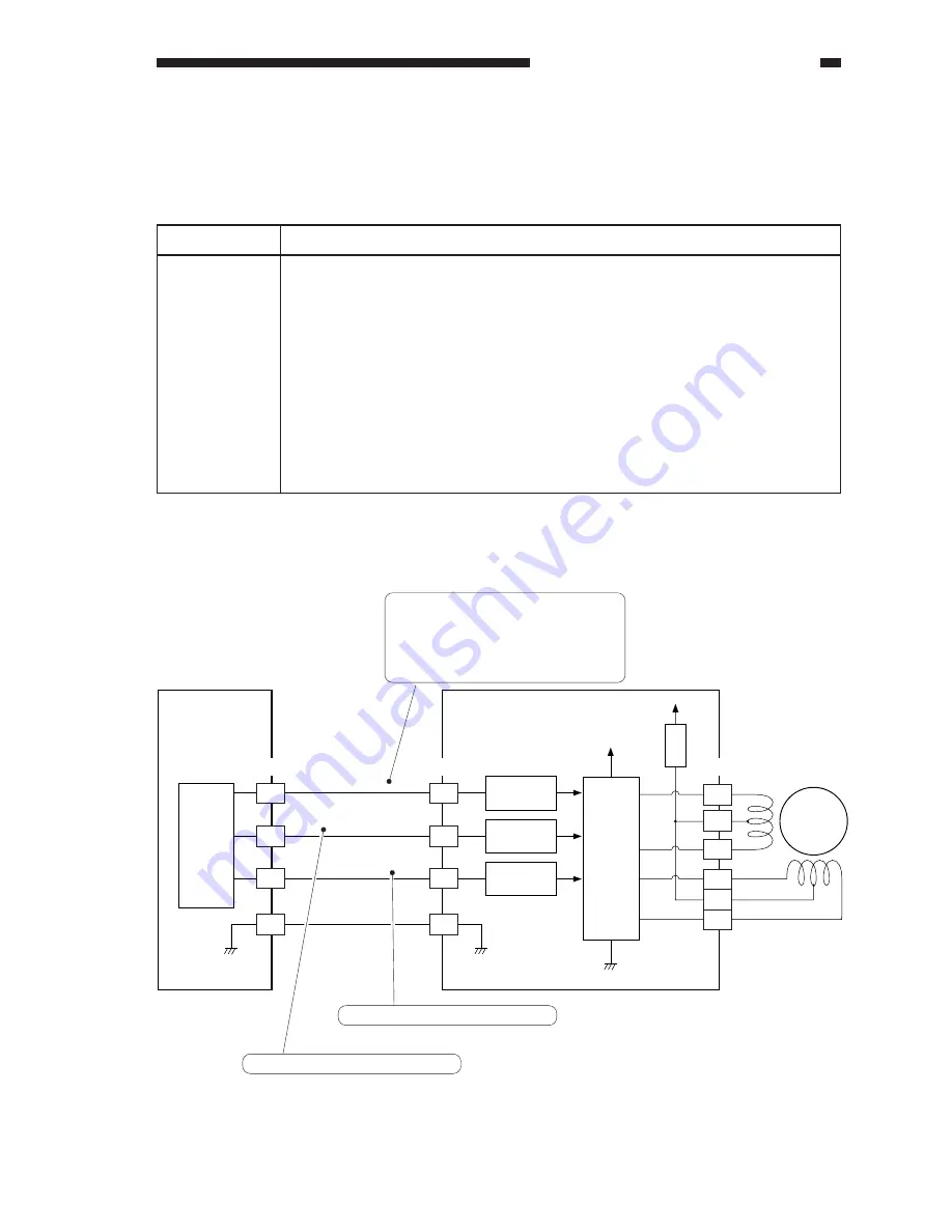
Controlling the Reversal Motor (M11)
1.
Outline
Table 7-401 shows the function of the reversal motor control circuit, and Figure 7-404 is a
block diagram of the circuit.
Table 7-401
Figure 7-404
Motor
driver
(IC1)
+24V
+24V
A
A*
B
B*
M11
A9
A11
A8
A7
A10
A6
FU3
Interface
circuit
Interface
circuit
Interface
circuit
A5
A6
A7
A8
A8
A7
A6
A5
J3602
J519
J3603
DUPI-OFF
DUPI-B
DUPI-A
DC controller
PCB
No-stacking feeding
driver PCB
CPU
(IC13)
Phase B excitation control signal
Phase A excitation control signal
When the M11 drive signal goes '1',
the pickup motor starts to rotate.
When the M11 drive signal goes '0',
the pickup motor stops.
Description
Supplies 24 V from the no-stacking feeder driver PCB.
Signal (DUPI_OFF) from the DC controller PCB.
See Figure 7-401.
ON/OFF control
Direction control
No error code; however, if a fault in the drive of the motor, a jam will occur.
Item
Power supply
Drive signal
Operating/drive
assembly
Control
Error detection
Содержание GP605
Страница 3: ......
Страница 4: ......
Страница 24: ......
Страница 56: ......
Страница 78: ......
Страница 116: ......
Страница 124: ......
Страница 148: ......
Страница 150: ......
Страница 168: ......
Страница 170: ......
Страница 250: ......
Страница 252: ......
Страница 342: ......
Страница 390: ......
Страница 392: ......
Страница 464: ......
Страница 466: ......
Страница 512: ......
Страница 514: ......
Страница 572: ......
Страница 574: ......
Страница 590: ......
Страница 592: ......
Страница 657: ...COPYRIGHT 1999 CANON INC CANON GP605 605V REV 0 JAN 1999 PRINTED IN JAPAN IMPRIME AU JAPON 13 65 ...
Страница 854: ......
Страница 870: ......
Страница 874: ......