


COPYRIGHT © 1999 CANON INC.
CANON GP605/605V REV.0 JAN. 1999 PRINTED IN JAPAN (IMPRIME AU JAPON)
6-5
CHAPTER 6 IMAGE FORMATION SYSTEM
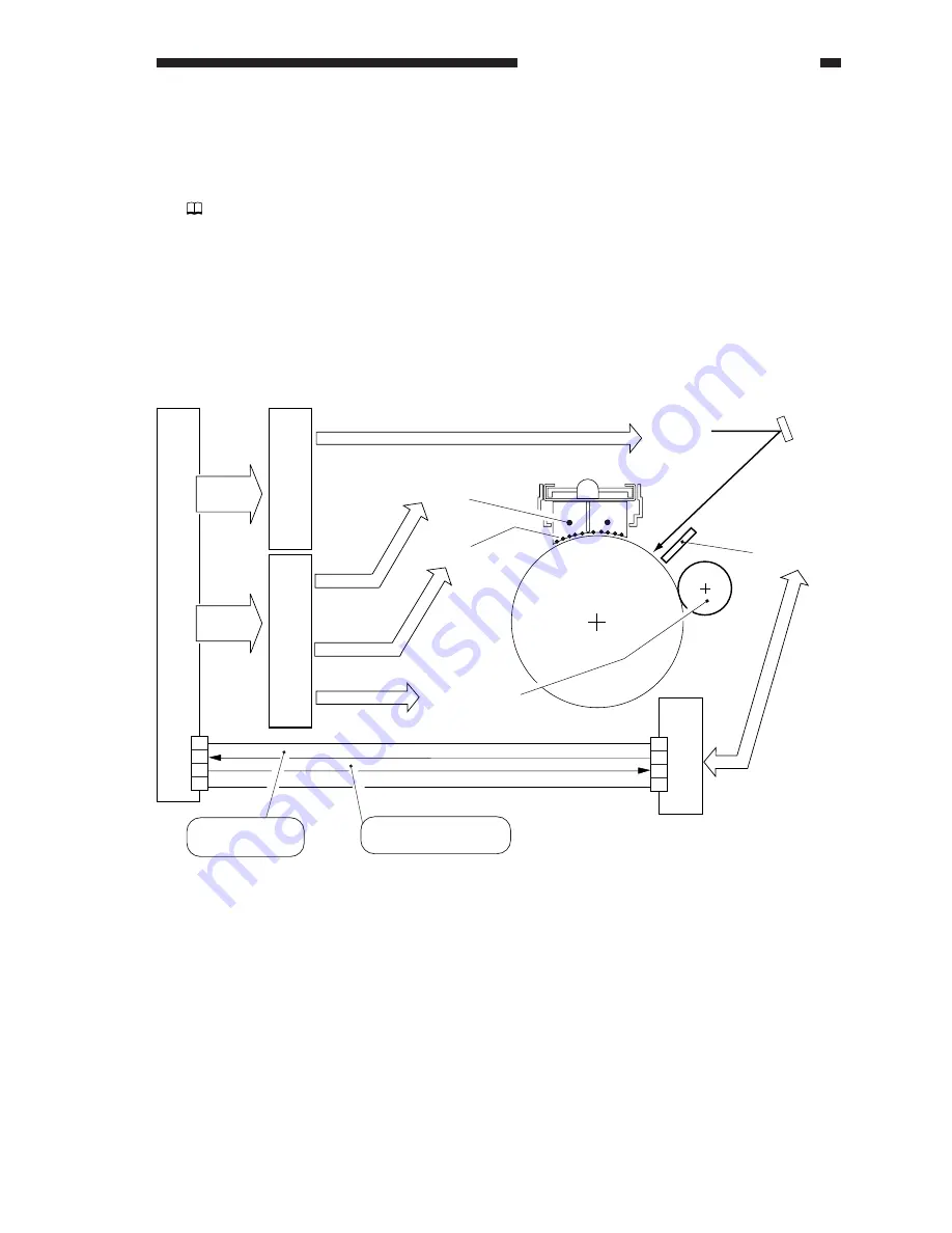
Figure 6-201 Construction of the Control System
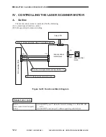
II . POTENTIAL CONTROL
A.
Outline
Volume 2>Chapter 4>I.B. "Controlling the Surface Potential of the Drum"
The potential is controlled for the following:
[1] Determining the optimum grid bias. (VD control)
[2] Determining the optimum laser output. (VL control)
[3] Determining the optimum developing bias (DC). (Vdc control)
Figure 6-201 shows the construction of the control system:
Primary charging wire
Potential sensor
Grid wire
Laser light
Developing cylinder
DC controller PCB
Laser driver PCB
High-voltage DC PCB
DC bias
DC bias
DC bias
Control
signal
Control
signal
Detection signal
J502
J3
11
12
13
14
4
3
2
1
0 V
24 VU
POT-DT
POT-ON
Potential control
PCB
Drum surface
potential reading
When '1', the potential
sensor turns on.
Содержание GP605
Страница 3: ......
Страница 4: ......
Страница 24: ......
Страница 56: ......
Страница 78: ......
Страница 116: ......
Страница 124: ......
Страница 148: ......
Страница 150: ......
Страница 168: ......
Страница 170: ......
Страница 250: ......
Страница 252: ......
Страница 342: ......
Страница 390: ......
Страница 392: ......
Страница 464: ......
Страница 466: ......
Страница 512: ......
Страница 514: ......
Страница 572: ......
Страница 574: ......
Страница 590: ......
Страница 592: ......
Страница 657: ...COPYRIGHT 1999 CANON INC CANON GP605 605V REV 0 JAN 1999 PRINTED IN JAPAN IMPRIME AU JAPON 13 65 ...
Страница 854: ......
Страница 870: ......
Страница 874: ......