background image

COPYRIGHT © 2001 CANON INC. 

2000 2000 2000 2000

 NM-PDL REV.0 JULY 2001

CHAPTER 4 DISASSEMBLY/ASSEMBLY

4-13

4 Electrical Parts

4.1 Outline

This section describes the procedure for removing and replacing the following boards:
• User interface board (UIB)
• Copier interface board
• Motherboard

For information on installing option boards, such as the Token Ring board, see the sepa-

rate installation instructions provided with that board.

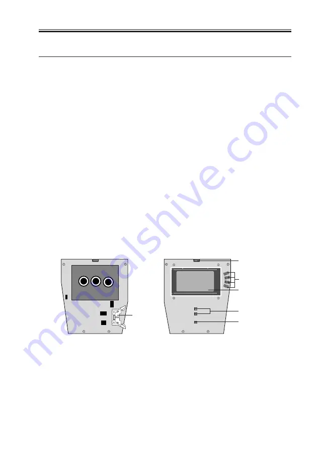
4.2 User Interface Board

The UIB installed in the front panel of the iR-M1 (see F04-402-01) provides the interface

between the iR-M1 and the user. The front of the user interface board contains circuitry for
the following:

• Activity lights (1 green and 1 red LED)
• Display window (LCD)
• Four line selection buttons
• Up and down button
• Menu button

The UIB cable connects to the cable connector on the back of the UIB and to

motherboard connector J30.

F04-402-01 User interface board layout

UIB cable 
connector 
(UIB cable 
connects 
to motherboard)

Activity lights (LEDs)

Line selection 
button pads

Display window

Up and down 
button pads

Menu button pad

Back

Front

Содержание FY8-13HR-000

Страница 1: ...REVISION 0 FY8 13HR 000 COPYRIGHT 2001 CANON INC NM PDL REV 0 JULY 2001 PRINTED IN U S A Network Multi PDL Printer Unit M1 image PASS M1 JULY 2001 ...

Страница 2: ...NED HEREIN MAY DIFFER SLIGHTLY FROM ACTUAL MACHINE VALUES OR THOSE FOUND IN ADVERTISING AND OTHER PRINTED MATTER ANY QUESTIONS REGARDING INFORMATION CONTAINED HEREIN SHOULD BE DIRECTED TO THE COPIER SERVICE DEPARTMENT OF THE SALES COMPANY COPYRIGHT 2001 CANON INC Printed in U S A CAUTION Use of this manual should be strictly supervised to avoid disclosure of confidential information ...

Страница 3: ... the iR M1 Chapter 1 Introduction General information about the iR M1 Chapter 2 Preparing for Installation Unpacking and the steps you need to take before you install the unit Chapter 3 Connecting the iR M1 How to connect the iR M1 to the copier and the network and verify that the system is working correctly overview of Control Panel Chapter 4 Service Procedures Removal and replacement procedures ...

Страница 4: ... disk surrounding the display window The term system software refers to the software installed on the iR M1 hard disk drive The term PC refers to any IBM PC or compatible computer running Windows The term 10BaseT is used throughout this manual to refer to 10BaseTX The term 100BaseT is used throughout this manual to refer to 100BaseTX References to other iR M1 manuals such as the Configuration Guid...

Страница 5: ... Installation 3 1 1 1 Preliminary Checkout 3 1 1 1 1 To Connect Power and Start the iR M1 3 1 1 2 Connecting to the Copier 3 3 1 2 1 To Connect the iR M1 to the Copier 3 3 1 3 Verifying the Connection 3 4 1 3 1 Printing the iR M1 Test Pages 3 4 1 4 Installing Additional Options 3 5 1 5 Connecting to the Network 3 5 1 5 1 To Connect a Twisted Pair Cable to the iR M1 3 6 2 Connecting a PC to the Par...

Страница 6: ...face Board 4 16 4 3 1 To Remove the Copier Interface Board 4 16 4 3 2 To Replace the Copier Interface Board 4 16 4 4 Motherboard 4 17 4 4 1 Removing the iR M1 Motherboard 4 18 4 5 Replacing Parts on the Motherboard 4 20 4 5 1 DIMM 4 20 4 5 2 Motherboard Battery 4 21 4 6 Fans 4 22 4 6 1 Exhaust Fan 4 22 4 6 2 CPU Fan 4 24 4 6 3 Power Switch 4 25 4 7 Power Supply 4 28 4 7 1 To Remove the Power Suppl...

Страница 7: ...Unit 5 8 2 1 To Isolate the iR M1 5 8 2 2 General iR M1 System Error Conditions 5 8 3 iR M1 Diagnostic Sets 5 11 3 1 To Run iR M1 Start Up Diagnostics 5 11 3 2 To Run iR M1 Custom Diagnostics 5 12 4 Checking the Entire iR M1 System 5 14 4 1 Checking the Copier Interface 5 14 4 1 1 Printing the Test Pages 5 14 4 2 Checking Network Connections 5 15 4 3 Printing to the iR M1 5 16 1 Specifications A 1...

Страница 8: ...upervisor 3 Never enter an IP address in iR M1 Network Setup Only the network administrator should enter an IP address on a network device Assigning a iR M1 an incorrect IP address can cause unpredictable errors on any or all devices connected to the network 4 Always disconnect power before opening the iR M1 chassis Although iR M1 circuitry operates on 3 3V DC 5V DC and 12V DC 100 240V AC is prese...

Страница 9: ... possible Attach a grounding strap to your wrist Attach the other end to a good ground When you unpack the iR M1 from the carton for the first time touch a metal area to discharge the static on your body Before you handle internal components touch a metal part of the iR M1 Leave new electronic components inside their antistatic bags until you are ready to install them When you remove components fr...

Страница 10: ... tools ESD wrist grounding strap Antistatic mat Wire cutters 1 and 2 Phillips head screwdrivers non magnetic Small flat blade screwdriver non magnetic 3 16 hex nut driver Small needlenose pliers M3 metric wrench Flashlight Also recommended Ribbon cable connector extractor You should also bring this guide and any technical notes you may have for the iR M1 ...

Страница 11: ...COPYRIGHT 2001 CANON INC 2000 2000 2000 2000 NM PDL REV 0 JULY 2001 CHAPTER 1 INTRODUCTION ...

Страница 12: ...age of printing features of Macintosh and Windows 95 98 Me Windows NT and Windows 2000 Professional Send images over AppleTalk TCP IP and Novell networks and print to a iR M1 sup ported copier Send images through a PC connected to the parallel port and print to a iR M1 sup ported copier Spool print jobs and select a printing priority for each job Use iR M1 user software running on networked PC and...

Страница 13: ...he iR M1 uses a specialized motherboard to process image data for printing images The motherboard includes a Intel Mobile Pentium III 500MHz CPU The PostScript Interpreter interprets the page description file The RipChip on the motherboard controls data man agement and other system functions freeing up the CPU for efficient image data processing High speed DIMMs dual in line memory modules on the ...

Страница 14: ... files at full copier speeds Users printing over a network can print files directly from the applications in which they were created The iR M1 also offers an efficient way to print files that have been saved in PostScript Encapsulated PostScript EPS or Portable Document Format PDF These files can be downloaded directly to the iR M1 using Fiery Downloader a remote utility pro vided with the iR M1 U...

Страница 15: ...r Software CD Some of the software can also be installed from the Fiery WebTools Installer see Getting Started for more information on WebTools The network administrator or the user at the customer site is responsible for in stalling software onto computers that will use the iR M1 over a network The following software is included on the User Software CD ...

Страница 16: ...R 1 INTRODUCTION 1 5 5 Fiery WebTools The iR M1 can support Internet or intranet access with Fiery WebTools WebTools in clude Status WebSpooler Installer WebDownloader WebSetup and WebLink For more information about WebTools see the Configuration Guide and the Printing Guide ...

Страница 17: ...COPYRIGHT 2001 CANON INC 2000 2000 2000 2000 NM PDL REV 0 JULY 2001 CHAPTER 2 PREPARING FOR INSTALLATION ...

Страница 18: ...ce described in this chapter is designed to make your job as easy as possible Installation problems are easier to avoid and diagnose if you proceed from the component to the system level and verify functionality at each stage F02 100 01 on page 2 2 outlines the recommended installation procedure for connecting the iR M1 to the copier Because the iR M1 is a node on the customer s computer network m...

Страница 19: ...nect copier interface cable page 3 3 Print the iR M1 Test Pages page 3 4 Connect a PC to the iR M1 parallel port page 3 7 Verify network operation without the iR M1 connected Network administrator connects the iR M1 to the network and verifies the connection see the Configuration Guide Network administrator configures Setup options see the Configuration Guide Network administrator installs the iR ...

Страница 20: ...re you install the iR M1 If the copied image indicates that the copier needs adjustment inform the customer After getting approval complete the copier service needed 2 2 Power Is there a dedicated grounded electrical outlet near the copier for the iR M1 Locate the grounded electrical outlet that will supply power to the iR M1 The iR M1 and the copier should not run on the same circuit Use a surge ...

Страница 21: ...d printer over the net work Ask the network administrator to verify the computer and network requirements as specified in Getting Started 2 4 Parallel Port Is there space for both the iR M1 and the PC that will be connected to the iR M1 If system software installation is required and will be done over the parallel port Can the parallel port on the PC be configured for ECP mode Is the PC running Wi...

Страница 22: ...nnector in place before the date scheduled for the iR M1 installa tion The network administrator should have a networked computer available during the installation The appropriate software should already be installed Documentation for the networked computer and the network operating software should be available The network administrator should install the user software shipped with the iR M1 onto ...

Страница 23: ...ower cable and copier interface cable iR M1 media package includes the user documentation 3 Give the media package to the customer or the network administrator Let the customer or network administrator know that in order to take full advantage of the iR M1 user software must be installed on all computers that will print to it 4 Set aside the remaining components from the top container 5 Remove the...

Страница 24: ...2000 2000 NM PDL REV 0 JULY 2001 CHAPTER 2 PREPARING FOR INSTALLATION 2 7 F02 301 01 Contents of the iR M1 shipping box iR M1 Power cable Copier interface cable Cross Ethernet cable Parallel cable Media package Network Interface Adapter ...

Страница 25: ...e iR M1 you can familiarize yourself with the front and back of the iR M1 before you install it F02 302 01 Front and back panels Jewels Activity light Line selection buttons Display window Up and down button Menu button Copier interface port Not used Not used Not used RJ 45 port network connection Parallel port Power connector Power switch Front Back ...

Страница 26: ...COPYRIGHT 2001 CANON INC 2000 2000 2000 2000 NM PDL REV 0 JULY 2001 CHAPTER 3 INSTALLATION ...

Страница 27: ...so includes information on Control Panel screens and icons 1 1 Preliminary Checkout When you have just unpacked or serviced a iR M1 power it on before you connect it to the copier and the network Diagnostics are run automatically during startup the iR M1 is checked for internal problems 1 1 1 To Connect Power and Start the iR M1 1 Connect the recessed end of the iR M1 power cable to the power conn...

Страница 28: ...you select the language the system reboots and beings initializing the system in that language To select a language different from the one initially highlighted on the Control Panel use the up and down buttons to scroll through the list and select OK when the desired language is highlighted 6 Allow the system to proceed to Idle to confirm that the iR M1 is operating correctly Once the iR M1 reache...

Страница 29: ... Copier Before connect the iR M1 to the copier install the Ethernee Network Interface Adapter to the copier 1 Power off the iR M1 as described on page 3 15 2 Power on the copier and set 1 to COPIER OPTION INT FACE IMG CONT in Service Mode 3 Power off the copier 4 Locate the copier interface cable Connect one end of the cable to the iR M1 interface port on the copier 5 Connect the other end of the ...

Страница 30: ...tch on the back panel Messages will appear on the Control Panel as the iR M1 runs through its Start up diag nostics 3 Before proceeding make sure that the copier is not in use 4 At the Idle screen press the menu button see Using the Control Panel on page 3 9 The Functions menu displays F03 103 01 5 Press the line selection button to the right of Print Pages and then select PS Test Page The iR M1 s...

Страница 31: ...ou to pinpoint the cause of problems should they occur 1 5 Connecting to the Network Ethernet support is built into the iR M1 motherboard providing connectivity to Ethernet networks Supported Ethernet cabling includes unshielded twisted pair for 10 100BaseT The motherboard in the iR M1 has one external Ethernet network RJ 45 port for 10 100BaseT twisted pair see F03 105 01 For network configuratio...

Страница 32: ... net work and user environment Default settings in Setup are adequate although they may not be optimal for the user s environment Refer the network administrator to the Con figuration Guide for Setup information 4 After configuring Setup options verify the network connection Once the network connection has been made and the iR M1 has the correct Setup con figuration the iR M1 should be available o...

Страница 33: ...ce for connecting directly to the parallel port of a stand alone or networked PC through the parallel cable The parallel cable used to connect these devices is included in the iR M1 shipping box 2 1 To Connect the iR M1 to a PC 1 Power off the iR M1 as described on page 3 15 2 Connect the parallel cable to the parallel port on the back panel of the iR M1 F03 201 01 iR M1 parallel port Parallel por...

Страница 34: ...Power on the PC and the iR M1 5 Configure Setup options It is the network administrator s responsibility to configure Setup according to the net work and user environment Default settings in Setup are adequate although they may not be optimal for the user s environment Refer the network administrator to the Con figuration Guide for Setup information 6 After Setup options are configured verify the ...

Страница 35: ...ol Panel to access and monitor different functions of the iR M1 The current status of the iR M1 and Setup information are displayed in the iR M1 display window iR M1 activity can be monitored in the display window and iR M1 functions such as printing a Test Page and installing or updating system software can be controlled locally using the buttons on the Control Panel F03 202 01 Control Panel Acti...

Страница 36: ...stics processing or printing a job or communicating with a remote com puter No light The iR M1 may be powered off or in Diagnostic Sets mode 2 2 2 Buttons Line selection buttons There are four line selection buttons on the right side of the Control Panel Use these buttons to select the command dis played on the corresponding line of the display window A special character pointing to a line selecti...

Страница 37: ...The bottom line of the screen displays the name of the current screen with the icon for that screen highlighted Icons for other active screens are also displayed but are not high lighted The iR M1 screens display the following information F03 202 02 Control Panel screens during printing If an error occurs the Alert screen is displayed with a message describing the error Server Name Idle 1047MB X 0...

Страница 38: ... selected It displays the following information Server Name The name entered for the iR M1 during Setup Status The current status of the iR M1 The iR M1 status can be Idle Initializing Busy Processing or Printing Number of MB The space in megabytes available on the iR M1 hard disk Version The system software version running on the iR M1 Print Status When the iR M1 is printing the Print Status scre...

Страница 39: ...s currently being processed Kilobytes The amount in kilobytes of the job that has been pro cessed so far Functions Menu The Functions menu is always available but it appears in the display window only when the user has pressed the Menu button to select it the icon is a finger pointing down to press a button If necessary use the up and down button to scroll through the list of menu com mands Press ...

Страница 40: ...cale samples to troubleshoot problems with the copier or the iR M1 The following information also displays iR M1 server name defined in Setup printer model date and time printed and compression infor mation see Printing the iR M1 Test Pages on page 3 4 Configuration Prints the Configuration page which gives the current server and de vice configuration This page lists general information about the ...

Страница 41: ...nel the iR M1 is currently processing a print job Wait until the job is complete and Idle appears in the Info screen 2 Press the menu button once then select Reboot Server At the next screen select Shut Down System Shutdown in progress appears on the Control Panel About 30 seconds later the message It is now safe to power off the system appears 3 Power off the iR M1 using the power switch on the b...

Страница 42: ...COPYRIGHT 2001 CANON INC 2000 2000 2000 2000 NM PDL REV 0 JULY 2001 CHAPTER 4 DISASSEMBLY ASSEMBLY ...

Страница 43: ...01 on page 4 2 for an overview of components Replacement parts are avail able from your authorized service representative Inside the chassis the power supply is not encased Before you service the iR M1 power it off completely and unplug the AC power cable from the back When performing the service procedures described in this chapter follow all precautions listed in Precautions on page v Memo The t...

Страница 44: ... 19 Key 1 Chassis cover 2 HDD carrier 3 Hard disk drive HDD 4 HDD cable 5 Copier interface board 6 DIMM 7 Motherboard 8 Center frame 9 EMI shield 10 Fans and power switch assembly 11 Fan cables 12 AC power cable 13 Ground cables 14 Power supply 15 Power supply cable 16 UIB enclosure 17 UIB cable 18 UIB 19 Front panel F04 102 01 iR M1 exploded view ...

Страница 45: ...M1 is currently processing a print job Wait until the job is complete and Idle appears in the Info screen 2 Press the menu button once then select Reboot Server At the next screen select Shut Down System Shutdown in progress appears on the Control Panel About 30 seconds later the message It is now safe to power off the system appears 3 Power off the iR M1 using the power switch on the back panel 4...

Страница 46: ...ls 2 1 To Open the iR M1 1 Make sure you have shut down the iR M1 as described on page 4 3 and removed all the cables from the back 2 Remove the four screws on the back of the iR M1 that secure the center frame with motherboard and devices attached to the chassis cover see F04 201 01 F04 201 01 Opening the iR M1 ...

Страница 47: ...otherboard and all devices are still attached to the center frame F04 201 02 Removing the chassis cover 6 Place the front panel face down on protective foam and set aside the chassis cover Most components on the center frame of the iR M1 are now directly accessible Remember to attach an ESD wrist strap before handling internal parts Inside the chassis the power supply is not encased Before you ser...

Страница 48: ...el 2 2 1 To Remove the Front Panel 1 Power off and open the iR M1 as described on F04 201 02 and page 4 4 2 Remove the four screws that secure the center frame to the front panel At this point the UIB cable attached to the motherboard keeps the front panel from be ing completely removed 3 Remove the UIB cable from motherboard connector J30 4 Thread the cable through its slot in the EMI shield F04 ...

Страница 49: ...ont panel face down on protective foam 3 Place the center frame on top of the front panel Thread the UIB cable through the UIB cable slot in the main EMI shield and center frame 4 Align the center frame with the four standoffs inside the front panel F04 202 02 Inside front panel 5 Attach the center frame to the front panel with four screws 6 Firmly attach the UIB cable to motherboard connector J30...

Страница 50: ...y parts inside the iR M1 chassis attach an ESD wrist grounding strap Touch the metal back panel of the iR M1 to discharge static electricity 3 1 To Check Board and Cable Connections 1 Power off and open the iR M1 as described on page 4 3 and page 4 4 2 Inspect ribbon cables to make sure they are intact Check the contact point between the cable and the connector to ensure that they have not separat...

Страница 51: ...or Power supply 6 pin connector Chassis ground pin Power supply 2 pin AC power connector To a Fan connector J25 on the motherboard b Fan connector J26 on the motherboard HDD connector on motherboard J28 UIB connector on motherboard J30 a Power connector on HDD 4 pin connector b Power connector on motherboard J29 a Power supply ground pin b Power switch pin E a Connector pin N on the power switch b...

Страница 52: ...and reseat it DIMMs fit into the sockets only one way A DIMM is fully seated in its socket when the levers close securely around the ends Avoid flexing the motherboard while you insert the DIMM in its socket 3 To release a DIMM push outward on the levers on each side of the DIMM see F04 302 01 F04 302 01 Releasing a DIMM 4 Slide the DIMM straight out of the socket 5 To install a DIMM slide it stra...

Страница 53: ... the front panel center frame assembly above the open chassis cover and then lower it gently into the chassis cover see F04 303 01 Fold in the fan cables AC power cable and HDD cable if necessary to avoid interfer ing with the closure and fraying the cables F04 303 01 Reassembling the iR M1 5 Make sure the edges are tight between the front panel and the chassis cover and then snap them together Th...

Страница 54: ... the fans Leaving the chassis cover off could reduce the operational life expectancy of internal iR M1 components 7 Verify iR M1 operation as outlined below Note that the iR M1 must be powered off before any cables are attached to the back panel F04 303 02 iR M1 connection verification steps Power on the iR M1 alone to check startup see page 3 1 Connect the iR M1 to the copier see page 3 3 Connect...

Страница 55: ...nterface Board The UIB installed in the front panel of the iR M1 see F04 402 01 provides the interface between the iR M1 and the user The front of the user interface board contains circuitry for the following Activity lights 1 green and 1 red LED Display window LCD Four line selection buttons Up and down button Menu button The UIB cable connects to the cable connector on the back of the UIB and to...

Страница 56: ...hread the UIB cable back through the UIB cable slot Set aside the UIB enclosure F04 402 02 Removing the UIB 4 Disconnect the UIB cable from the cable connector on the back of the UIB see F04 402 01 on page 4 13 5 Remove the four screws that secure the UIB to the inside front panel see F04 402 02 Lift the UIB out of the front panel Set aside the screws for reassembly and place the UIB in an antista...

Страница 57: ...or on the UIB making sure to lock it in place using the levers see F04 402 03 F04 402 03 UIB cable connector 4 Position the UIB enclosure above the front panel and thread the UIB cable through the UIB cable slot 5 Install the UIB enclosure When properly aligned the eight notches on the UIB enclosure fit over the eight guides molded along the inside edge of the front panel Tuck in all the loose met...

Страница 58: ...nel as described on page 4 6 2 Remove the screw on the side of the port bracket that secures the copier interface board to the port bracket 3 Remove the copier interface board from motherboard connector J17 Grasp the board at the sides Gently pull the board straight up until it releases from the connector 4 Place the copier interface board in an antistatic bag 4 3 2 To Replace the Copier Interface...

Страница 59: ...l devices This section includes instructions for replacing the motherboard motherboard battery and DIMMs F04 404 01 Diagram of the iR M1 motherboard Key 1 RJ 45 port J4 2 Parallel port J2 3 BIOS chip 4 Battery BT1 5 Cpoier interface board connector J17 6 Exhaust fan cable connector J25 7 Exhaust fan cable connector J26 8 HDD cable connector J28 9 UIB cable connector J30 10 CPU heatsink CPU fan 11 ...

Страница 60: ...on the iR M1 HDD Along with the fonts provided on the System Software CD the customer may have installed additional fonts that will be deleted when the motherboard is replaced 2 Power off and open the iR M1 as described on page 4 3 and page 4 4 3 For stability during service remove the front panel as described on page 4 6 4 Remove the power supply cable from motherboard connector J29 5 Remove the ...

Страница 61: ...nnector J29 4 Reseat any option board removed from motherboard connector J18 5 Reseat the copier interface board on motherboard connector J17 see To remove the copier interface board on page 4 16 6 Attach the two fan cables to motherboard connectors J25 and J26 7 Attach the UIB cable to motherboard connector J30 8 Attach the HDD cable to motherboard connector J28 9 Reattach the front panel as desc...

Страница 62: ...et on the motherboard The iR M1 is originally configured for a minimum of 128MB a To Replace a DIMM 1 To release a DIMM push outward on the levers on each side of the DIMM see F04 405 01 F04 405 01 Releasing a DIMM 2 Slide the DIMM straight out of the socket 3 To replace a DIMM slide it straight into the socket and close the levers on each side to lock it into place A DIMM fits in the socket only ...

Страница 63: ...orgt werden Il y a risque d explosion si la pile est remplacée par un modèle qui ne convient pas Remplacez la uniquement par le modèle recommandé par le constructeur Débarrassez vous des piles usées conformément aux instructions du constructeur a To Replace the Motherboard Battery 1 Locate the battery on the motherboard 2 Carefully lift up the clip that holds the battery Use caution when lifting u...

Страница 64: ...aches to motherboard connector J27 You should hear the fans start as soon as you power on the iR M1 4 6 1 Exhaust Fan Use the following procedures to service the exhaust fans a To Remove the Exhaust Fans 1 Power off and open the iR M1 as described on page 4 3 and page 4 4 2 For stability during service remove the front panel as described on page 4 6 3 Remove the exhaust fan cables from motherboard...

Страница 65: ...els on the fans in F04 406 01 on page 4 22 2 Secure the fan to the metal bracket with the three screws previously removed 3 Attach the fan cables to motherboard connectors J25 and J26 Use a tie wrap to secure the fan cables to the white tie mount on the metal bracket Fold any excess cable neatly and secure with a tie wrap 4 If you removed the front panel reattach it as described on page 4 7 5 Reas...

Страница 66: ...tor J27 F04 406 02 CPU fan a To Remove the CPU Fan 1 Power off and open the iR M1 as described on page 4 3 and page 4 4 2 Remove the CPU fan cable from iR M1 board connector J27 see F04 406 03 To remove the fan cable gently pull the white connector from the pins 3 Using a Phillips screwdriver remove the four screws that secure the CPU fan to the CPU heatsink Set aside the screws so that you can re...

Страница 67: ...Do not to apply excessive pressure to the board when replacing the screws 3 Connect the CPU fan cable to iR M1 board connector J27 4 Reassemble the iR M1 and verify its functionality as described on page 4 11 4 6 3 Power Switch The power switch is mounted on a metal bracket attached to the device side of the center frame The following cables connect to the power switch AC power cable Ground cable ...

Страница 68: ...rom the pins on the power switch Leave the other end of the cable attached to the power supply 5 Remove the ground cable green from its pin on the power switch see F04 406 04 on page 4 25 Leave the other end of the cable attached to the chassis ground pin 6 Remove the two screws that secure the power switch to the metal bracket 7 Remove the ground shield 8 Remove the power switch by lifting it up ...

Страница 69: ... 05 Power switch pins and cables 5 Connect the ground cable to pin E on the power switch see F04 406 05 The other end of the ground cable should still be attached to the chassis ground pin The second ground cable should remain attached to the chassis ground pin and the power supply 6 Reattach the front panel as described on page 4 7 7 Reassemble the iR M1 and verify its functionality as described ...

Страница 70: ...Power supply cable with connectors to the HDD and motherboard The power supply cable supplies 5V 12V and 12V to the motherboard and 5V and 12V to the HDD see Power supply cable voltages on page 4 31 Ground cables Inside the chassis the power supply is not encased Before you service the iR M1 power it off and unplug the power cable from the back F04 407 01 Power supply on the center frame Chassis g...

Страница 71: ...able attached to the pins on the power switch 5 Remove the ground cable green from the power supply with a pair of needlenose pli ers Leave the other end of the ground cable attached to the chassis ground pin 6 Remove the four screws that secure the power supply to the center frame 7 Remove the power supply from the center frame 4 7 2 To Replace the Power Supply 1 Secure the power supply to the ce...

Страница 72: ...the power switch F04 407 02 Power supply pins and cables 6 Connect the ground cable to the power supply ground pin The ground cable should still be attached to the chassis ground pin 7 Fit the bottom EMI shield into the main EMI shield and secure it with two screws 8 Reattach the front panel as described on page 4 7 9 Reassemble the iR M1 and verify its functionality as described on page 4 11 Chas...

Страница 73: ...r supply and motherboard Memo Do not attempt to measure voltages on the power supply cable F04 407 03 Power supply cable voltages 4 pin HDD 6 pin motherboard 6 pin power supply Connector Pin number Cable color DC Voltage 1 Yellow 12V 2 Black Common 3 Black Common 4 Red 5V 1 Yellow 12V 2 Red 5V 3 Red 5V 4 Black Common 5 Black Common 6 Blue 12V 1 Blue 12V 2 Black Common 3 Black Common 4 Red 5V 5 Red...

Страница 74: ...re replacing the HDD with a new drive print the following from the Functions menu Configuration page records the customer s current Setup configuration If you are installing a new drive you will need to reinstall system software The Setup configuration will be reset to the default configuration when HDD is replaced Font Lists details what PostScript and PCL fonts are resident on the iR M1 HDD Alon...

Страница 75: ...o make it easier to connect the cable slide the HDD carrier in only part way 4 Attach the power supply cable to the HDD 5 Continue sliding the HDD carrier onto the center frame until the release tab clicks into place 6 Attach the HDD cable to motherboard connector J28 Align the connectors and push the HDD cable connector straight in to avoid bending pins on the motherboard Straighten any bent pins...

Страница 76: ...t Panel Components The front panel contains jewels the UIB and buttons This section describes replacing jewels and buttons in the front panel For information on replacing the UIB see User inter face board on page 4 13 F04 409 01 iR M1 jewels and buttons Line selection buttons Up and down button Menu button Jewels ...

Страница 77: ...il it snaps into place 5 Reattach the front panel as described on page 4 7 6 Reassemble the iR M1 and verify its functionality as described on page 4 11 4 9 2 Buttons The two sets of Control Panel buttons are designed to fit only one way in their respective cutouts in the front panel In position the buttons make contact with the button pads on the UIB to provide users with manual status control fe...

Страница 78: ... The Download Tool is a program used to download system software from a PC to the Board The program used to write system software obtained from a PC through the parallel port to the HDD is stored in the flash ROM of the Board 5 1 Download Tool 5 1 1 Outline The Download Tool is made available in the form of a self decompressing file To install the system software it is first necessary to install t...

Страница 79: ...tation IEEE 1284 Std compliant System software CD ROM 5 2 3 Preparing the iR M1 Installation of the system software will clear the existing settings As preparatory work print out the Configuration page 1 Press the Menu button 2 Select Print page 3 Select Configuration 4 When the configuration page indicating the settings information of the iR M1 has been printed keep it at hand for use after the i...

Страница 80: ... press the up botton on the front of the iR M1 3 At the parallel boot screen on the iR M1 select Yes If you do not select Yes quickly enough at the parallel boot screen recycle power and try again 4 When the message Send download has appeared perform step 4 in 5 2 7 Operating the PC 5 Perform setp 5 to step 6 of 5 7 2 Operating the PC 6 At the Choose Function screen select Instllation A message ap...

Страница 81: ...COPYRIGHT 2001 CANON INC 2000 2000 2000 2000 NM PDL REV 0 JULY 2001 CHAPTER 5 TROUBLESHOOTING ...

Страница 82: ...as you should check out before making a service call to the customer site With a phone call you can find out if the problem is a simple operating failure or a failure caused by a network or configura tion change You can ask the customer to check for loose cables on the back of the iR M1 and loose connections at a power strip or outlet Check for obvious causes of problems Preliminary on site checko...

Страница 83: ...e of three areas Inside the iR M1 In the interface between the iR M1 and the copier In the interface between the iR M1 and the network or PC to which it is connected F05 102 01 Troubleshooting the system This chapter does not attempt to provide troubleshooting information for attached PCs or Mac OS computers for copiers or for extensive networks You should refer problems in these areas to the appr...

Страница 84: ...s there a printing problem Does the iR M1 Test Page fail to print Does the iR M1 fail to respond to a print command Does printing seem to take a long time Is print quality poor Does the iR M1 fail to appear in the list of printers Has the customer noted any error messages on the iR M1 or the copier screen If the answer to any of these questions is yes refer the customer to the Printing Guide If th...

Страница 85: ...eration of the iR M1 If so obtain a list of the modifications This should direct you toward possible problem areas For example if the HDD has been replaced system software may need to be rein stalled 5 Is the user having printing problems with a particular image file If there are problems with files from particular applications the user may be more suc cessful using different print settings See th...

Страница 86: ...ce port and con nected to the copier see Connecting to the copier on page 3 3 If a PC is connected check that the parallel cable is connected to the PC and the iR M1 parallel port see Connecting a PC to the parallel port on page 3 7 Check that the network cable is connected to the proper port on the back panel see Connecting to the network on page 3 5 Make sure the power cable is plugged into the ...

Страница 87: ...n page 4 3 2 Before you touch any components inside the iR M1 chassis attach an ESD grounding strap to your wrist Discharge any static electricity on your body by touching the metal back panel of the iR M1 3 Inspect the inside of the chassis Check the connections between an option board if present and the motherboard If a board is loose reseat it securely in its connector Check the connections bet...

Страница 88: ... 9 2 3 4 11 10 15 14 13 12 16 17 18 19 Key 1 Chassis cover 2 HDD carrier 3 Hard disk drive HDD 4 HDD cable 5 Copier interface board 6 DIMM 7 Motherboard 8 Center frame 9 EMI shield 10 Fans and power switch assembly 11 Fan cables 12 AC power cable 13 Ground cables 14 Power supply 15 Power supply cable 16 UIB enclosure 17 UIB cable 18 UIB 19 Front panel ...

Страница 89: ...1 Copier interface cable Network cable Parallel cable if a PC is connected to the parallel port 2 Make sure the power cable to the iR M1 is still in place 2 2 General iR M1 System Error Conditions When you startup the iR M1 or when you install system software you may encounter er ror conditions T05 202 01 lists some of these error conditions and suggests corrective ac tion When you first encounter...

Страница 90: ... to the power supply and power switch see Internal cable connections on page 4 9 If the above does not correct the problem replace the power supply see Power supply on page 4 28 Check the UIB cable connection to the UIB and motherboard see User interface board on page 4 13 If the problem persists replace the UIB cable If the problem still persists replace the UIB Make sure that the DIMM s are inse...

Страница 91: ...stalled back panel of the iR M1 backwards Suggested action Check to make sure that the buttons are installed correctly and are making contact with the pads on the UIB see User interface board on page 4 13 Check the UIB cable connection to the UIB and motherboard see User interface board on page 4 13 Make sure that the UIB is installed correctly and that the UIB enclosure is in place If the problem...

Страница 92: ... button on the Control Panel 3 Power on the iR M1 4 Release the up button as soon as you see the Choose Function screen display F05 301 01 5 Select Diagnostics from the Choose Function screen 6 When prompted choose Startup from the Diagnostics menu Diagnostics begin immedi ately F05 301 02 7 If no Diagnostics fail the iR M1 boots up normally If a test fails the name of the test appears on the Disp...

Страница 93: ...ears All diagnostic tests are marked with an X if there is a diagnostic test that you do not want to run press the button next to the name to remove the X When the desired tests are selected press the button next to Continue F05 302 03 Diagnostics Continue Boot Installation Clear Server Choose Function Select to proceed to the Diagnostics menu Select to resume iR M1 startup Select to begin system ...

Страница 94: ...imme diately F05 302 05 11 If no Diagnostics fail the iR M1 boots up normally If a test fails the name of the test appears on the Display Window 12 If a test fails replace the motherboard F05 302 06 iR M1 diagnostic overview Continue X DEC PCI Bridge X VID Video Chip X SCSI Chip Run Tests Until All Tests Done First Test Fails Select to run all tests and then view any failures after complete Select...

Страница 95: ...properly to the copier The PS and PCL Test Pages are black and white PostScript files that reside on the iR M1 hard disk drive Print both pages to make sure ev erything is operating properly a To Print the Test Page From the Control Panel 1 Power on the copier and allow it to warm up 2 Power on the iR M1 using the power switch on the back panel Messages appear on the Control Panel as the iR M1 run...

Страница 96: ...re is not set up properly or doesn t match network settings on the iR M1 Problems may also occur when printing from a specific application or printing a particular file Most of these problems show up as printing problems and do not necessarily indicate a iR M1 malfunction The customer s network administrator can eliminate many printing problems without requiring you to make a service call The netw...

Страница 97: ...r printers Checked the corrective actions listed in the user documentation shipped with the iR M1 Confirmed that the applicable network settings in Setup such as AppleTalk zone IP address Subnet mask and Gateway address match the settings used in the network When you make a service call check the back panel of the iR M1 to make sure that the appropriate network connections are in place Intermitten...

Страница 98: ...COPYRIGHT 2001 CANON INC 2000 2000 2000 2000 NM PDL REV 0 JULY 2001 CHAPTER 6 PARTS CATALOG ...

Страница 99: ...CHAPTER 6 PARTS CATALOG 6 1 COPYRIGHT 2001 CANON INC 2000 2000 2000 2000 NM PDL REV 0 JULY 2001 ...

Страница 100: ...COPYRIGHT 2001 CANON INC 2000 2000 2000 2000 NM PDL REV 0 JULY 2001 CHAPTER 6 PARTS CATALOG 6 2 FIGURE 100 image PASS M1 Network Multi PDL Printer Unit M1 17 1 2 3 4 5 6 7 8 9 11 10 12 12 12 14 16 15 13 ...

Страница 101: ...0 1 DIMM 128MB 5 FE1 5556 000 1 POWER SUPPLY PCB ASSEMBLY 6 FE1 5557 000 2 FAN 7 FE1 5558 000 1 HDD UNIT 10GB 8 FE1 5559 000 1 PLATE LOGO 9 FE1 5560 000 1 PLATE LOGO 10 FE1 5561 000 1 COVER TOP 11 FE1 5562 000 1 COVER CHASSIS 12 FE1 5563 000 1 POWER CORD 120V 120V FE1 5564 000 1 POWER CORD 230V 220 240V FE1 5565 000 1 POWER CORD 203V 220 240V 13 FE1 5566 000 1 CABLE CROSS 14 FE1 5567 000 1 CABLE H...

Страница 102: ...COPYRIGHT 2001 CANON INC 2000 2000 2000 2000 NM PDL REV 0 JULY 2001 APPENDIX ...

Страница 103: ...networking features Supports AppleTalk TCP IP and IPX protocols simultaneously RJ 45 port for twisted pair 10 100BaseT network connection 1 3 User Software A complete description of iR M1 user software is provided in the Printing Guide For op timal iR M1 performance current versions of the user software should be maintained on ev ery network computer that might print to the iR M1 1 4 Safety and Em...

Страница 104: ...ANON INC NM PDL REV 0 JULY 2001 PRINTED IN U S A Prepared by Office Imaging Products Quality Assurance Center CANON INC Printed in U S A REVISION 0 JULY 2001 28353 5 1 Hakusan 7 chome Toride shi Ibaraki 302 8501 Japan ...

Страница 105: ...PRINTED IN U S A 0701AB00 This publication is printed on 100 recycled paper ...

Отзывы: