CT-MCL01 l User’s Manual
30
Chapter 1: Product Introductions
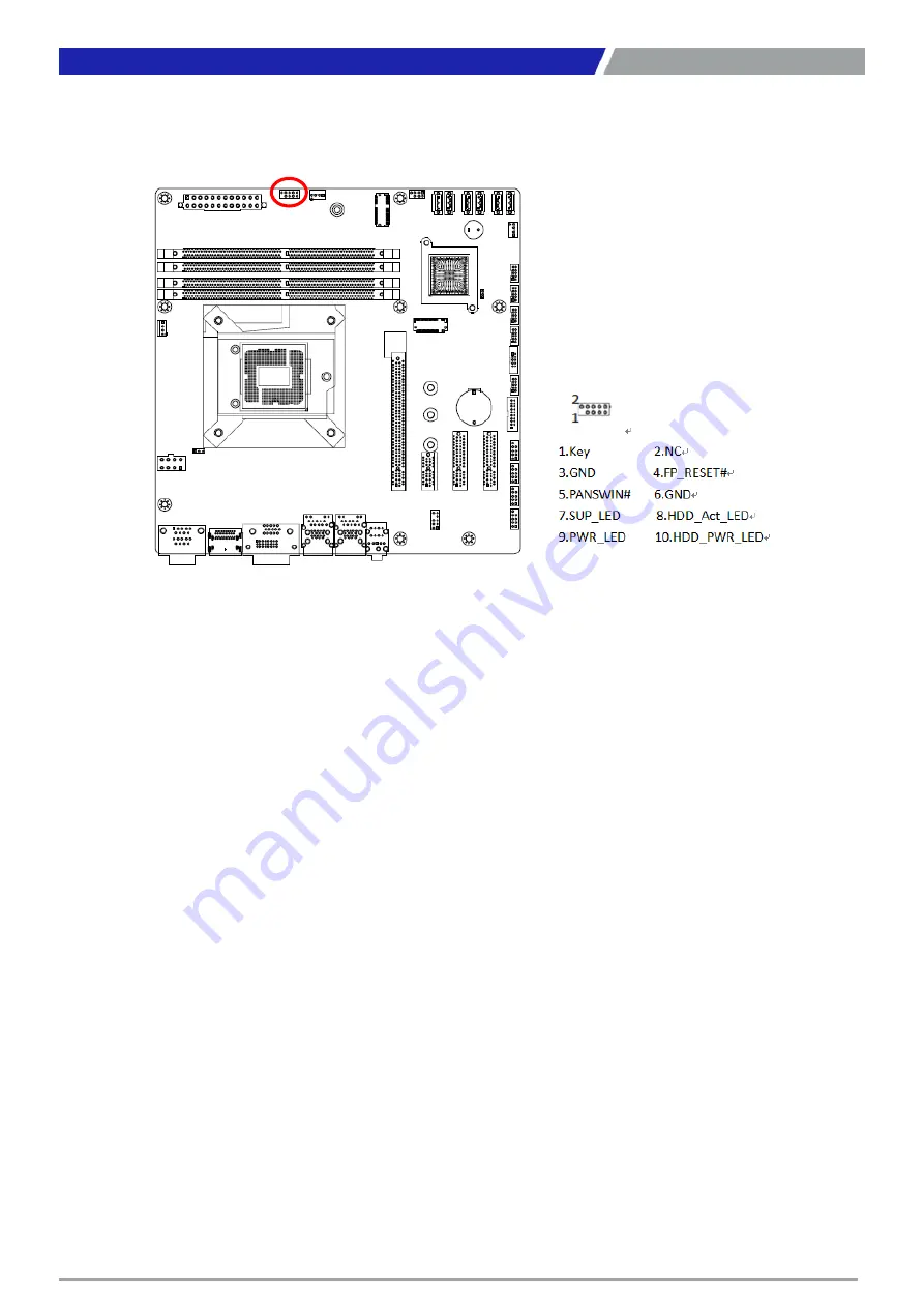
1.7.3 System Panel (F_PANEL1)
This connector is for a chassis-mounted front panel. The functions are as following.
ATX Power Button/Soft-off Button (Pin 3-5)
This 2-pin connector is for the system power button. Pressing the power button turns the system on
or puts the system in sleep or soft-off mode depending on the BIOS settings. Pressing the power
switch and holding it for more than four seconds while the system is ON turns the system OFF.
Reset Button (Pin 4-6)
This 2-pin connector is for the chassis-mounted reset button for system reboot without turning off
the system power.
Power LED (Pin 7-9)
This 2-pin connector is for the system power LED. Connect the chassis power LED cable to this
connector. The system power LED lights up when you turn on the system power, and blinks when
the system is in sleep mode.
Hard Disk Drive Activity LED (Pin 8-10)
This 2-pin connector is for the HDD Activity LED. Connect the HDD Activity LED cable to this
connector. The IDE LED lights up or flashes when data is read from or written to the HDD.
Содержание CT-MCL01 Series
Страница 1: ...CT MCL01 Series Micro ATX Industrial Motherboard...
Страница 8: ...CT MCL01 l User s Manual 8 Block Diagram...
Страница 9: ...Chapter 1 Product Introductions...
Страница 12: ...CT MCL01 l User s Manual 12 1 2 3 Motherboards Layout Chapter 1 Product Introductions...
Страница 44: ...CT MCL01 l User s Manual 44 2 11 1 CPU Configuration 2 11 2 Power Performance Chapter 2 BIOS Setup...
Страница 45: ...CT MCL01 l User s Manual 45 Chapter 2 BIOS Setup...
Страница 46: ...CT MCL01 l User s Manual 46 2 11 3 PCH FW Configuration 2 11 4 ACPI Settings Chapter 2 BIOS Setup...
Страница 47: ...CT MCL01 l User s Manual 47 2 11 5 NCT6106D Super IO Configuration Chapter 2 BIOS Setup...
Страница 48: ...CT MCL01 l User s Manual 48 Chapter 2 BIOS Setup...
Страница 49: ...CT MCL01 l User s Manual 49 Chapter 2 BIOS Setup...
Страница 50: ...CT MCL01 l User s Manual 50 Chapter 2 BIOS Setup...
Страница 51: ...CT MCL01 l User s Manual 51 2 11 6 NCT6106D HW Monitor Chapter 2 BIOS Setup...
Страница 52: ...CT MCL01 l User s Manual 52 Chapter 2 BIOS Setup 2 11 7 Trusted Computing...
Страница 54: ...CT MCL01 l User s Manual 54 2 11 10 Intel TXT Information 2 11 11 USB Configuration Chapter 2 BIOS Setup...
Страница 55: ...CT MCL01 l User s Manual 55 2 11 12 CSM Configuration 2 11 13 NVME Configuration Chapter 2 BIOS Setup...
Страница 56: ...CT MCL01 l User s Manual 56 2 11 14 Network Stack Configuration Chapter 2 BIOS Setup...
Страница 57: ...CT MCL01 l User s Manual 57 2 12 Chipset 2 12 1 System Agent SA Configuration Chapter 2 BIOS Setup...
Страница 58: ...CT MCL01 l User s Manual 58 Chapter 2 BIOS Setup...
Страница 59: ...CT MCL01 l User s Manual 59 Chapter 2 BIOS Setup 2 12 2 PCH IO Configuration...
Страница 60: ...CT MCL01 l User s Manual 60 Chapter 2 BIOS Setup...
Страница 61: ...CT MCL01 l User s Manual 61 Chapter 2 BIOS Setup...
Страница 62: ...CT MCL01 l User s Manual 62 Chapter 2 BIOS Setup...
Страница 63: ...CT MCL01 l User s Manual 63 Chapter 2 BIOS Setup...
Страница 64: ...CT MCL01 l User s Manual 64 Chapter 2 BIOS Setup...
Страница 65: ...CT MCL01 l User s Manual 65 2 13 Security 2 13 1 Secure Boot Chapter 2 BIOS Setup...
Страница 66: ...CT MCL01 l User s Manual 66 Chapter 2 BIOS Setup 2 14 Boot...
Страница 67: ...CT MCL01 l User s Manual 67 2 15 Save Exit Chapter 2 BIOS Setup...
Страница 72: ...Copyright 2016 C T Solution Inc All Rights Reserved www candtsolution com...


