C-1
Appendix C. Monitoring Sampler Status
via RS-485
When controlling a sampler via time-based/stand-alone or pulse control, it is
possible to still collect the sampler status values over RS-485 (PakBus® or
Modbus®). The following sections walk through configuring the MD485 to
talk with a CR1000 and then programming examples for Modbus® and
PakBus® in
CRBasic
.
C.1 Configuring an MD485
1. Connect a serial cable to the RS-232 port on the MD485 and to the
computer.
2. Supply power (12 Vdc) to the MD485 by the power jack or through the
+12 V line on the CS I/O connector. You will need a SC12 serial cable to
connect the CS I/O port of the MD485 to the CS I/O port on the
datalogger.
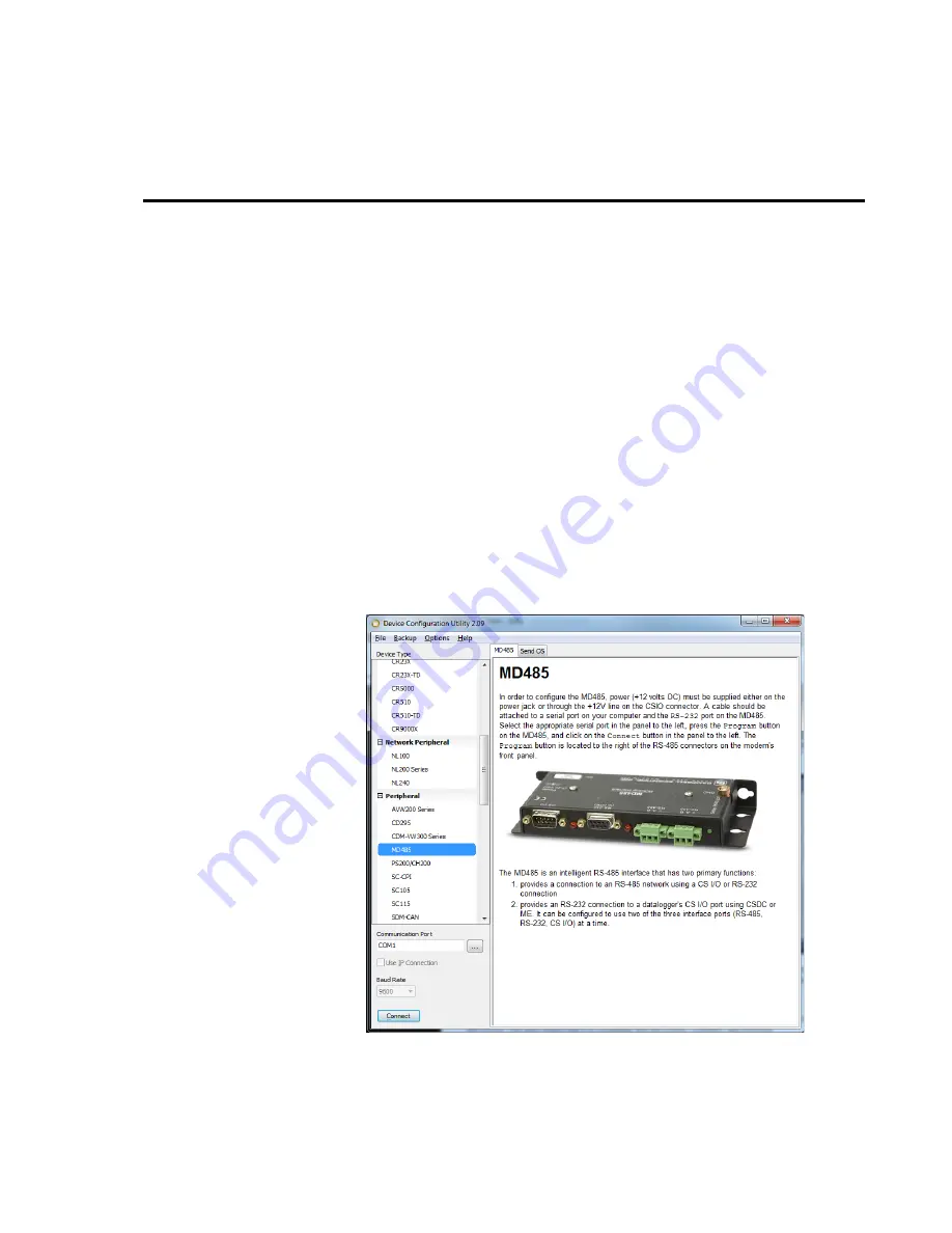
3. Open
DevConfig
. Click
Peripheral
. Select
MD485
. Select the
Communication Port
. Push the
Program
button on the MD485. Click
Connect
. The program button is located to the right of the RS-485
connectors on the modem’s front panel.
FIGURE C-1. MD485 Device Configuration screen
Содержание PVS5120 Series
Страница 2: ......
Страница 4: ......
Страница 6: ......
Страница 8: ......
Страница 70: ...Appendix A Sample Transport Velocity A 2...
Страница 78: ...Appendix B Example Programs B 8...
Страница 86: ...Appendix C Monitoring Sampler Status via RS 485 C 8...
Страница 96: ...Appendix G Generic Modbus Control G 4...
Страница 100: ...Appendix H ISO5667 Conformity H 4...
Страница 101: ......


