B
120 min
C max
27,5
A
310 max
p.
41
- M
an
ua
l
FA
00
441
-E
N
- 0
8/
20
18 - © C
AM
E S
.p
.A
. -
Tr
an
sla
tio
n o
f t
he o
rig
in
al i
ns
tru
ct
io
ns
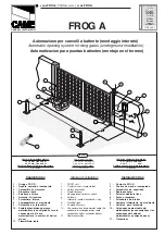
CHECKING MEASUREMENTS AND APPLICATIVE DIMENSIONS
Establish where you will fit the gate brace and measure where the gate-post brace will fit. Make sure to respect
the quotas shown in the drawing and table.
Leaf opening arc (°)
A
B
C max
90
140
420
60
110
140
420
60
INWARD OPENING CONNECTIONS AND INSTALLING
Following, are the only things that change compared to a standard installation:
ERROR MESSAGE
The error messages are shown on the display.
E1
The travel calibration was interrupted when the STOP button was activated
E2
Calibrating the complete gate-travel
E3
Encoder broken
E4
Services test error
E7
Insufficient working time
E9
Closing obstruction
E10
Opening obstruction
E11
Maximum number of detected obstructions
E14
Serial communication error
E15
Incompatible transmitter error
E17
Wireless system error
E18
The wireless system is not configured


