background image

Pa

g.


44

 - C

od

ic

e m

an

u

al

e:


F

A

0

0

0

9

5

-I

T

F

A

00095

-I

T

 - ve

r.


44

 - 0

8

/2

0

17 - © C

am

e S

.p.

A

. - I c

onte

n

uti d

el m

an

u

al

e s

on

o d

a r

ite

n

er

si s

u

sc

etti

b

ili

 d

i m

od

ifi

ca

 in

 q

u

al

si

as

i m

om

ento s

en

za

 o

b

b

lig

o d

i p

re

avvi

so

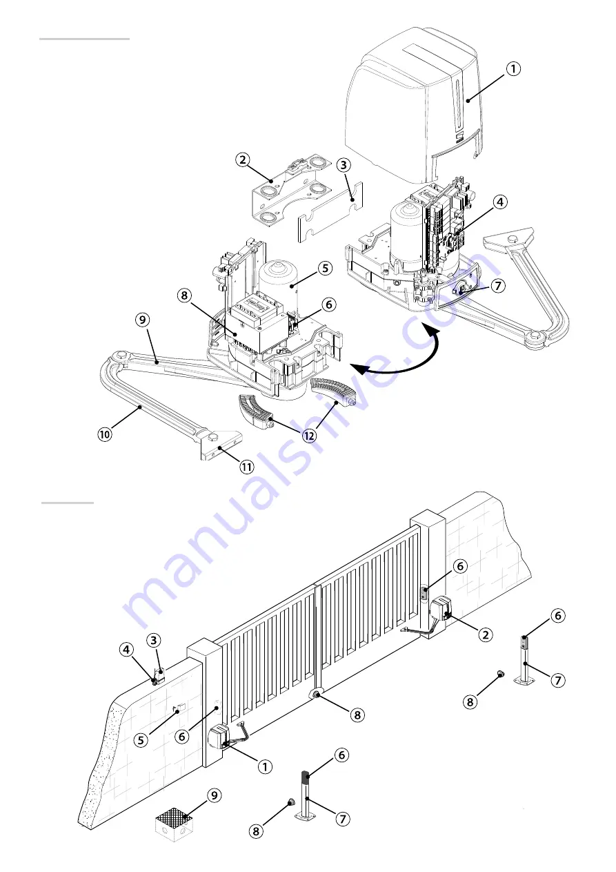
Impianto tipo

1. 

Automazione

2. 

Motoriduttore

3. 

Lampeggiatore

4. 

Antenna

5. 

Dispositivo di comando

6. 

Fotocellule

7. 

Colonnina per fotocellule

8. 

Battuta di arresto

9. 

Pozzetto di derivazione

Descrizione delle parti

1. 

Coperchio

2. 

Staff a pilastro

3. 

Spessore in gomma

4. 

Scheda elettronica

5. 

Motoriduttore

6. 

Morsetto di alimentazione

7. 

Sportello di sblocco

8. 

Trasformatore

9. 

Braccio di trasmissione

10. 

Braccio condotto

11. 

Staff a cancello

12. 

Fermi meccanici

Содержание FAST 70

Страница 1: ...Automazione per cancelli a battente FA7024CB MANUALE D INSTALLAZIONE IT Italiano EN English FR Fran ais RU P FA00095M04...

Страница 2: ...IONI E RACCOMANDAZIONI PARTICOLARI PER GLI UTENTI TENERE LIBERE DA INGOMBRI E PULITE LE AREE DI MANOVRA DEL CANCELLO CONTROLLARE CHE NON VI SIA VEGETAZIONE NEL RAGGIO D AZIONE DELLE FOTOCELLULE E CHE...

Страница 3: ...di isolamento I Peso kg 12 DESCRIZIONE Automazione irreversibile completa di scheda elettronica con display gar co a segmenti e braccio di trasmissione snodato per cancelli a battente no a 2 3 m per...

Страница 4: ...Motoriduttore 3 Lampeggiatore 4 Antenna 5 Dispositivo di comando 6 Fotocellule 7 Colonnina per fotocellule 8 Battuta di arresto 9 Pozzetto di derivazione Descrizione delle parti 1 Coperchio 2 Staffa...

Страница 5: ...continuit del circuito di protezione siano provviste di isolamento supplementare rispetto ad altre parti conduttrici interne predisporre adeguate tubazioni e canaline per il passaggio dei cavi elettri...

Страница 6: ...i riferiscono all automazione installata a sinistra L installazione del motoriduttore a destra simmetrica Posa dei tubi corrugati Predisporre i tubi corrugati necessari per i collegamenti provenienti...

Страница 7: ...installatore scegliere la soluzione pi adatta a seconda del tipo e spessore dell anta Prima di installare l automazione rimuovere il coperchio nel seguente modo aprire il tappo di protezione del sport...

Страница 8: ...fica in qualsiasi momento senza obbligo di preavviso Fissaggio dell automazione Inserire il motoriduttore nella staffa pilastro e fissarlo con le viti e i dadi Inserire la spina nel foro dell albero m...

Страница 9: ...ondenza del centro del braccio Chiudere manualmente l anta Posizionare il fermo meccanico sotto la cassa Il segno sulla cassa deve corrispondere alla scanalatura sul fermo come illustrato Fissare il f...

Страница 10: ...odifica in qualsiasi momento senza obbligo di preavviso Determinazione dei punti di finecorsa Con il motoriduttore sbloccato e con l anta chiusa regolare il grano del finecorsa di chiusura girandolo i...

Страница 11: ...mory Roll 13 Display 14 Pulsanti di programmazione 15 Connettore per scheda RIO CONN 16 Connettore per scheda RSE 17 Morsettiera per modulo RGP1 18 Fusibile accessori 19 Trasformatore 20 Morsettiera d...

Страница 12: ...di comando Vedi funzione F 1 Funzione APRE CHIUDE INVERSIONE passo passo da dispositivo di comando contatto NO In alternativa dalla programmazione delle funzioni possibile attivare il comando APRE ST...

Страница 13: ...ione e del motoriduttore Collegamenti elettrici automazione installata a destra vista interna Collegamenti elettrici automazione installata a sinistra vista interna Predisposizione di default Collegam...

Страница 14: ...l contatto provoca l inversione del movimento no alla completa chiusura Se non vengono utilizzati i contatti CX e CY vanno disattivati in programmazione Dispositivi di sicurezza Fotocellule Con gurare...

Страница 15: ...curezza test sicurezza A ogni comando di apertura o di chiusura la scheda veri ca l efficienza dei dispositivi di sicurezza es fotocellule Un eventuale anomalia inibisce qualsiasi comando e a display...

Страница 16: ...ti servono per spostarsi da una voce di menu a un altra incrementare o decrementare un valore Display Per entrare nel menu tenere premuto il pulsante ENTER per almeno un secondo Per scegliere la voce...

Страница 17: ...la corsa F 35 Sensibilit durante il rallentamento F 36 Regolazione apertura parziale F 37 Regolazione punto iniziale di rallentamento in apertura del motoriduttore M1 F 38 Regolazione punto iniziale d...

Страница 18: ...Apertura parziale Dal dispositivo di comando collegato su 2 3P esegue l apertura pedonale apertura completa dell anta di M2 o apertura parziale apertura parziale dell anta di M2 il grado di apertura d...

Страница 19: ...o d ariete 1 1 secondo default 2 2 secondi Dopo un comando di apertura e chiusura il motoriduttore esegue una spinta in battuta per un tempo regolabile da 1 secondo a 2 secondi F 27 Tempo serratura 1...

Страница 20: ...Disattivata default 1 Attivata Salvataggio nella memory roll degli utenti e delle impostazioni memorizzate Questa funzione appare solo se nella scheda elettronica stata inserita una memory roll F 51...

Страница 21: ...op chiude stop 3 Comando solo apre 4 Comando parziale Inserimento no a un max di 25 utenti e associazione a ognuno di essi di una funzione a scelta tra quelle previste L inserimento va fatto con trasm...

Страница 22: ...d arresto meccanico in apertura e una in chiusura Le battute d arresto meccanico sono obbligatorie Importante Durante la taratura tutti dispositivi di sicurezza saranno disabilitati Selezionare A 3 P...

Страница 23: ...i per un eventuale utente da inserire max 25 utenti Selezionare U 1 Premere ENTER per confermare Selezionare un comando da associare all utente I comandi sono passo passo apre chiude 1 sequenziale apr...

Страница 24: ...to di inizio accostamento in apertura di M1 N Punto di inizio accostamento in apertura di M2 O Battute di arresto Minimo 600 mm dalla battuta di arresto Impostare la percentuale di accostamento dalla...

Страница 25: ...ione deve essere effettuata in assenza di tensione Lo sblocco manuale dell automazione pu causare un movimento incontrollato del cancello se questo presenta problemi meccanici o se non bilanciato OPER...

Страница 26: ...vizi E 7 Tempo lavoro insufficiente E 9 Ostacolo in chiusura E 10 Ostacolo in apertura E 11 Numero massimo di ostacoli rilevati E 14 Errore di comunicazione seriale E 17 Errore del sistema wireless E...

Страница 27: ...lmente l anta Posizionare il fermo meccanico sotto la cassa Il segno sulla cassa deve corrispondere alla scanalatura sul fermo come illustrato Fissare il fermo con la vite In chiusura Chiudere l anta...

Страница 28: ...e Collegamento dell automazione e del motoriduttore Collegamenti elettrici automazione installata a destra vista interna Collegamenti elettrici automazione installata a sinistra vista interna Collegam...

Страница 29: ...ca in qualsiasi momento senza obbligo di preavviso MANUTENZIONE Manutenzione periodica Prima di qualsiasi operazione di manutenzione togliere la tensione per evitare possibili situazioni di pericolo c...

Страница 30: ..._________________________________________________________________ _____________________________________________________________________________________________ Timbro installatore Nome operatore Data...

Страница 31: ...ono essere smaltiti senza alcuna difficolt semplicemente effettuando la raccolta differenziata per il riciclaggio Prima di procedere sempre opportuno verificare le normative specifiche vigenti nel luo...

Страница 32: ...t 15 31030 Dosson di Casier Treviso Italy tel 39 0422 4940 fax 39 0422 4941 Manuale FA00095 IT ver 4 08 2017 CAME S p A I contenuti del manuale sono da ritenersi suscettibili di modifica in qualsiasi...

Страница 33: ...Operator for swing gates FA7024CB INSTALLATION MANUAL EN English FA00095 EN...

Страница 34: ...AND IN A VISIBLE PLACE SUCH AS SUCH AS THE GATE S PLATE SPECIAL USER INSTRUCTIONS AND RECOMMENDATIONS KEEP GATE OPERATION AREAS CLEAN AND FREE OF ANY OBSTRUCTIONS MAKE SURE THAT THE PHOTOCELLS ARE FRE...

Страница 35: ...rature C 20 55 Insulation class I Weight Kg 12 DESCRIPTION Irreversible operator with control board and segmented graphic display plus jointed transmission arm for swing gates with leaves up to 2 3 m...

Страница 36: ...allation 1 Operator 2 Gearmotor 3 Flashing light 4 Antenna 5 Control device 6 Photocells 7 Photocells post 8 Mechanical gate stop 9 Junction pit Description of parts 1 Cover 2 Post bracket 3 Rubber sh...

Страница 37: ...ional insulation with respect to those of other electrical parts inside set up suitable tubes and conduits for the electric cables to pass through making sure they are protected from any mechanical da...

Страница 38: ...awing show an operator fitted on the left Install the operator on the right symmetrically Corrugate tube laying Lay the corrugated tubes you will need for the cables coming out of the junction pit The...

Страница 39: ...arefully choose the most suitable set up according to the type and thickness of the gate leaf Before fitting the operator remove the casing as follows open the release hatch protective cap fit the tri...

Страница 40: ...be changed at any time without prior notice Fastening the operator Fit the gearmotor into the gate post brace and tighten the nuts and bolts Fit the plug into the gearmotor s drive shaft hole Fasten...

Страница 41: ...y close the gate leaf Place the mechanical stop under the casing The mark on the case must match the groove on the stop as shown Fasten the stop using the screw Release the gearmotor see RELEASING THE...

Страница 42: ...me without prior notice Establishing the limit switch points With the gearmotor released and the gate leaf closed adjust the closing limit switch grub screw by turning it clockwise or counterclockwise...

Страница 43: ...buttons 15 Connector for the RIO CONN card 16 RSE board connector 17 Terminals for the RGP1 module 18 Accessories fuse 19 Transformer 20 Power supply terminal board 21 Line fuse 22 Housing for the CO...

Страница 44: ...ep from control device NO contact Alternatively from the functions programming you can activate the single command OPEN STOP CLOSE STOP sequential See function F7 B l u e White Connector for the R700...

Страница 45: ...e operator and gearmotor Electrical connections operator tted on the right inner view Electrical connections Operator installed on the left outer view Default setting Electrical connections operator i...

Страница 46: ...ing the contact triggers the inversion of movement until the gate is fully closed If contacts CX and CY are not used they should be deactivated during programming Safety devices Photocells Con gure co...

Страница 47: ...e the safety test At each opening and closing command the control board checks the efficacy of the safety devices such as photocells Any malfunction will inhibit any command and E 4 will appear on the...

Страница 48: ...ys are for moving from one item to another increasing or decreasing values Display To enter the menu keep the ENTER button pressed for at least one second To select menu items use the arrow keys then...

Страница 49: ...vement F 35 Sensitivity during slow down F 36 Adjusting partial opening F 37 Adjusting the M1 gearmotor s opening slow down start point F 38 Adjusting the M1 gearmotor s closing slow down start point...

Страница 50: ...or sequential open stop close stop command F 8 Command 2 3P 0 Pedestrian opening default 1 Partial opening From the control device connected to 2 3P it performs the pedestrian opening completely open...

Страница 51: ...ic lock releases for an adjustable time between one and four seconds F 28 Travel speed 60 Minimum speed 100 Maximum speeddefault Setting the gate s opening and closing speeds calculated as a percentag...

Страница 52: ...s been tted into the control board F 56 Peripheral number 1 225 To set the peripheral s number from 1 to 255 for each control board when you have a system with several operators F 63 Changing COM spee...

Страница 53: ...tion chosen among the existing ones This must be done via transmitter or other control device see ENTERING USERS WITH ASSOCIATED COMMAND paragraph U 2 Deleting a user Deleting a single user U 3 Deleti...

Страница 54: ...that there are mechanical opening and closing stops The mechanical end stops are obligatory Important During calibration all safety devices will be disabled Select A 3 Press ENTER to con rm Select 1 a...

Страница 55: ...users you may wish to enter maxi mum 25 users Select U 1 Press ENTER to con rm Select a command to associate to the user The commands are step step open close 1 sequential open stop close stop 2 open...

Страница 56: ...slow down starting point for M1 N Opening slow down starting point for M1 O Strike plates Minimum 600 mm from the strike plate Set the closing rest percentage for function F 39 F 40 for the rst motor...

Страница 57: ...e done with the main power cut off Manually releasing the operator may result in uncontrolled movement of the gate if this has any mechanical problems or is unbalanced FINAL OPERATIONS Once you have n...

Страница 58: ...nsufficient working time E 9 Closing obstruction E 10 Opening obstruction E 11 Maximum number of detected obstructions E 14 Serial communication error E 17 Wireless system error E 18 The wireless syst...

Страница 59: ...lose the gate leaf Place the mechanical stop under the casing The mark on the case must match the groove on the stop as shown Fasten the stop using the screw When closing Close the leaf Mark the casin...

Страница 60: ...Connecting the operator and gearmotor Electrical connections operator fitted on the right inner view Electrical connections Operator installed on the left outer view Electrical connections operator i...

Страница 61: ...ay be changed at any time without prior notice MAINTENANCE Periodic maintenance Before doing any maintenance cut off the power supply to prevent any hazardous situations caused by accidentally activat...

Страница 62: ..._________________ ________________________________________________________________________________________ Fitter s stamp Name of operator Job performed on date Technician s signature Requester s sign...

Страница 63: ...lid urban waste and simply separated from other waste for recycling Always make sure you comply with local laws before dismantling and disposing of the product DO NOT DISPOSE OF IN NATURE DISMANTLING...

Страница 64: ...ia Martiri Della Libert 15 31030 Dosson di Casier Treviso Italy tel 39 0422 4940 fax 39 0422 4941 Manuale FA00095 EN ver 4 08 2017 CAME S p A The contents of this manual may change at any time and wit...

Страница 65: ...Automatisme pour portails battants FA7024CB MANUEL D INSTALLATION FR Fran ais FA00095 FR...

Страница 66: ...NS PARTICULI RES POUR LES UTILISATEURS D GAGER ET NETTOYER LES ZONES D ACTIONNEMENT DU PORTAIL S ASSURER DE L ABSENCE DE TOUTE V G TATION DANS LE RAYON D ACTION DES PHOTOCELLULES ET DE TOUT OBSTACLE D...

Страница 67: ...55 Classe d isolation I Poids Kg 12 DESCRIPTION Automatisme irr versible avec carte lectronique afficheur segments et bras de transmission articul pour portails battants jusqu 2 3 m par vantail Utili...

Страница 68: ...2 Motor ducteur 3 Feu clignotant 4 Antenne 5 Dispositif de commande 6 Photocellules 7 Colonne pour photocellules 8 But e d arr t 9 Bo tier de d rivation Description des parties 1 Couvercle 2 trier pil...

Страница 69: ...dot es d une isolation suppl mentaire par rapport aux autres parties conductrices internes pr voir des tuyaux et des conduites pour le passage des c bles lectriques afin de les prot ger contre la d t...

Страница 70: ...iqu e Les dessins illustrent l automatisme install gauche L installation du motor ducteur droite est sym trique Pose des gaines annel es Pr voir les gaines annel es n cessaires pour les raccordements...

Страница 71: ...t choisir la solution la plus appropri e selon le type et l paisseur du vantail Avant d installer l automatisme enlever le couvercle de la fa on suivante Ouvrir le capuchon de protection du volet de d...

Страница 72: ...tout moment et sans aucun pr avis Fixation de l automatisme Introduire le motor ducteur dans l trier pilier et le fixer l aide des vis et des crous Introduire la cheville dans le trou de l arbre du mo...

Страница 73: ...ionner la but e m canique sous la caisse Le signe sur la caisse doit correspondre la rainure pr sente sur la but e comme illustr Fixer la but e l aide de la vis D bloquer le motor ducteur voir D BLOCA...

Страница 74: ...s aucun pr avis D termination des points de fin de course Avec motor ducteur d bloqu et vantail ferm r gler le goujon de la but e de fin de course de fermeture en le tournant dans le sens horaire ou a...

Страница 75: ...2 Connecteur pour carte Memory Roll 13 Afficheur 14 Boutons de programmation 15 Connecteur pour carte RIO CONN 16 Connecteur pour carte RSE 17 Bornier de connexion du module RGP1 18 Fusible accessoire...

Страница 76: ...nction OUVERTURE FERMETURE INVERSION pas pas depuis un dispositif de commande contact NO Il est galement possible d activer la commande OUVERTURE ARR T FERMETURE ARR T s quentielle depuis la programma...

Страница 77: ...du motor ducteur Branchements lectriques automatisme install droite vue interne Branchements lectriques automatisme install gauche vue interne Installation par d faut Branchements lectriques automatis...

Страница 78: ...inversion du mouvement jusqu fermeture totale du portail En cas de non utilisation des contacts CX et CY les d sactiver durant la phase d auto apprentissage Dispositifs de s curit Photocellules Con g...

Страница 79: ...it La carte contr le l efficacit des dispositifs de s curit ex photocellules chaque commande d ouverture ou de fermeture Toute ventuelle anomalie d sactive les commandes quelles qu elles soient et l c...

Страница 80: ...une option de menu l autre augmenter ou diminuer une valeur Afficheur Pour entrer dans le menu maintenir la touche ENTER enfonc e pendant au moins une seconde Pour choisir l option de menu se d place...

Страница 81: ...rant la course F 35 Sensibilit durant le ralentissement F 36 R glage ouverture partielle F 37 R glage point initial de ralentissement du motor ducteur M1 en ouverture F 38 R glage point initial de ral...

Страница 82: ...e pas pas ouverture fermeture inversion ou s quentielle ouverture arr t fermeture arr t F 8 Commande 2 3P 0 Ouverture pi tonne par d faut 1 Ouverture partielle Depuis le dispositif de commande connect...

Страница 83: ...t de fermeture la serrure lectrique se d bloque pendant un temps r glable entre 1 seconde et 4 secondes F 28 Vitesse course 60 Vitesse minimale 100 Vitesse maximale par d faut Con guration de la vites...

Страница 84: ...ion plusieurs automatismes F 63 Modi cation vitesse COM 0 1200 Bauds 1 2400 Bauds 2 4800 Bauds 3 9600 Bauds 4 14400 Bauds 5 19200 Bauds 6 38400 Bauds 7 57600 Bauds 8 115200 Bauds Pour la con guration...

Страница 85: ...oir paragraphe LIMINATION D UN SEUL UTILISATEUR U 3 limination utilisateurs 0 D sactiv e 1 limination de tous les utilisateurs limination de tous les utilisateurs A 1 Type moteur 1 SWN20 SWN25 par d f...

Страница 86: ...en l ouverture qu la fermeture Les but es d arr t m canique sont obligatoires Important Durant le r glage tous les dispositifs de s curit seront d sactiv s S lectionner A 3 Appuyer sur ENTER pour con...

Страница 87: ...l utilisateur ins rer max 25 utilisateurs S lectionner U 1 Appuyer sur ENTER pour con rmer S lectionner une commande associer l utilisateur Les commandes sont pas pas ouverture fermeture 1 s quentiell...

Страница 88: ...de rapprochement en ouverture de M2 O But es d arr t Minimum 600 mm de la but e d arr t Con gurer le pourcentage de rapprochement par le biais de la fonction F 39 F 40 pour le premier moteur M1 et de...

Страница 89: ...t d effectuer cette op ration Le d blocage manuel de l automatisme peut provoquer un mouvement incontr l du portail si ce dernier pr sente des probl mes m caniques ou s il n est pas quilibr OP RATIONS...

Страница 90: ...Temps de fonctionnement insuffisant E 9 Obstacle la fermeture E 10 Obstacle l ouverture E 11 Nombre maximum d obstacles d tect s E 14 Erreur de communication s rie E 17 Erreur du syst me sans l E 18 L...

Страница 91: ...ner la but e m canique sous la caisse Le signe sur la caisse doit correspondre la rainure pr sente sur la but e comme illustr Fixer la but e l aide de la vis En phase de fermeture Fermer le vantail Tr...

Страница 92: ...ion de l automatisme et du motor ducteur Branchements lectriques automatisme install droite vue interne Branchements lectriques automatisme install gauche vue interne Branchements lectriques automatis...

Страница 93: ...ns tout moment et sans aucun pr avis ENTRETIEN Entretien p riodique Avant toute autre op ration d entretien il est conseill de mettre hors tension pour viter toute situation de danger provoqu e par de...

Страница 94: ...________________________________________ _____________________________________________________________________________________________ Cachet installateur Nom op rateur Date intervention Signature tec...

Страница 95: ...difficult en proc dant tout simplement la collecte diff renci e pour le recyclage Avant d effectuer ces op rations il est toujours recommand de v rifier les normes sp cifiques en vigueur sur le lieu...

Страница 96: ...CAME S p A Via Martiri Della Libert 15 31030 Dosson di Casier Treviso Italy tel 39 0422 4940 fax 39 0422 4941...

Страница 97: ...A FA7024CB RU FA00095 RU...

Страница 98: ...2 2 FA00095 RU FA00095 RU 4 4 08 2017 Came S p A CAME S P A 2 5 20 1 85 1 5 EN 12453 8...

Страница 99: ...200 235 230 0 50 100 150 200 250 300 350 1 1 25 1 5 1 75 2 2 25 2 5 2 75 3 3 FA00095 RU FA00095 RU 4 4 08 2017 Came S p A FA7024CB IP 54 50 60 230 24 5 5 RGP1 0 5 140 180 90 13 30 C 20 55 I 12 2 3...

Страница 100: ...4 4 FA00095 RU FA00095 RU 4 4 08 2017 Came S p A 1 2 3 4 5 6 7 8 9 1 2 3 4 5 6 7 8 9 10 11 12...

Страница 101: ...2017 Came S p A STYLO BD 3 1 15 m 15 30 m 230 H05RN F 3G x 1 5 2 3G x 2 5 2 24 FROR CEI 20 22 CEI EN 50267 2 1 3 x 1 5 2 3 x 2 5 2 2 x 0 5 2 2 x 0 5 2 4 x 0 5 2 2 x 0 5 2 RG58 10 Came Remote Protocol...

Страница 102: ...173 94 40 120 100 60 18 A B 120 min C MAX 47 5 310 max 200 min 6 6 FA00095 RU FA00095 RU 4 4 08 2017 Came S p A A B 90 140 0 200 420 90 160 180 200 380 110 200 220 0 50 400...

Страница 103: ...7 7 FA00095 RU FA00095 RU 4 4 08 2017 Came S p A...

Страница 104: ...UNI 6593 14 UNI 5739 M10x14 12 UNI 6593 6 UNI 5739 M6x10 8 8 FA00095 RU FA00095 RU 4 4 08 2017 Came S p A...

Страница 105: ...UNI 5739 M6x10 UNI 6593 6 UNI 6592 12 12 9 9 FA00095 RU FA00095 RU 4 4 08 2017 Came S p A...

Страница 106: ...10 10 FA00095 RU FA00095 RU 4 4 08 2017 Came S p A...

Страница 107: ...11 11 FA00095 RU FA00095 RU 4 4 08 2017 Came S p A 1 2 3 4 5 CRP 6 7 8 9 CONNECT GW 10 AF 11 R700 R800 12 13 14 15 RIO CONN 16 RSE 17 RGP1 18 19 20 21 22 CONNECT GW 23 RGP1 24 RLB ZL65 2 A F 230 2 A 2...

Страница 108: ...o Rosso 10 11 E 5 M1 N1 ENC1 M2 N2 ENC2 1 2 3P 7 10 TS 2 CX CY A B GND S1 GND A B 12 12 FA00095 RU FA00095 RU 4 4 08 2017 Came S p A RG58 F 8 AF AF868 AF43S F 1 F 7 R700 R800 CONNECT GW CONNECT GW RGP...

Страница 109: ...M1 N1 ENC1 M2 N2 ENC2 FA7024CB FA7024 FA7024 FA7024CB M1 N1 ENC1 M2 N2 ENC2 M1 N1 ENC1 M2 N2 ENC2 M1 N1 ENC1 M2 N2 ENC2 M N E M N E 13 13 FA00095 RU FA00095 RU 4 4 08 2017 Came S p A...

Страница 110: ...CY DELTA 10 11 E 5 1 2 3P 7 10 TS 2 CX CY A B GND TX NO C NC DELTA S DIR 10 11 E 5 1 2 3P 7 10 TS 2 CX CY A B GND 14 14 FA00095 RU FA00095 RU 4 4 08 2017 Came S p A DFW DFI CX CY EN 12978 CX F2 CY F3...

Страница 111: ...S DIR RSE RIO CELL RIO EDGE RIO LUX A B GND 10 TS 2 CX CY A B GND S1 GND A B UTP CAT 5 1 2 3 4 1 2 3 4 RIO CONN TS 2 CX CY A B GND S1 GND A B 15 15 FA00095 RU FA00095 RU 4 4 08 2017 Came S p A RS485...

Страница 112: ...F i F i F 2 F 3 0 i 0 3 i 3 8 8 8 16 16 FA00095 RU FA00095 RU 4 4 08 2017 Came S p A ENTER ESC ENTER 1 ENTER 10 ESC ENTER ENTER...

Страница 113: ...F 9 F 10 F 11 F 12 F 13 F 14 F 16 F 18 F 19 F 20 F 21 F 22 F 23 F 24 F 26 F 27 F 28 F 30 F 33 F 34 F 35 F 36 F 37 1 F 38 1 F 39 1 F 40 1 F 41 2 F 42 2 F 43 2 F 44 2 F 46 F 49 F 50 F 51 F 56 F 63 COM F...

Страница 114: ...C1 2 C2 3 C3 4 C4 7 C7 8 C8 C1 C2 C3 C4 C7 C8 C3 F 19 F 3 2 CY 0 1 C1 2 C2 3 C3 4 C4 7 C7 8 C8 C1 C2 C3 C4 C7 C8 C3 F 19 F 5 0 1 CX 2 CY 4 CX CY F 6 0 1 2 3P 2 7 F 7 2 7 0 1 2 7 F 8 2 3 0 1 2 3 F36 F...

Страница 115: ...0 1 10 F 22 5 5 120 120 180 180 5 180 F 23 0 0 2 2 10 10 M1 1 2 F 24 0 0 5 5 25 25 2 1 5 F 26 1 1 2 2 1 2 F 27 1 1 4 4 1 4 F 28 60 100 FA7024CB 50 F 30 10 50 60 FA7024CB 30 F 33 20 50 60 F 34 10 100 F...

Страница 116: ...RP Came Remote Procotol F 50 0 1 F 51 0 1 F 56 1 225 1 255 F 63 COM 0 1200 1 2400 2 4800 3 9600 4 14400 5 19200 6 38400 7 57600 8 115200 CRP Came Remote Protocol F65 RIO EDGE T1 0 7 P7 8 P8 RIO EDGE P...

Страница 117: ...21 FA00095 RU FA00095 RU 4 4 08 2017 Came S p A 2 ENTER 1 ENTER M2 M1 RIO CELL P1 P2 P3 P4 RIO CONN U 1 1 2 3 4 25 U 2 U 3 0 1 A 1 1 SWN20 SWN25 2 FA7024CB A 2 0 1 A 3 0 1 A 4 0 1 A 5 0 1 001 100 010...

Страница 118: ...M2 M1 M2 M1 M2 M1 M2 M1 3 a i C l i o p i c l 2 o p 2 22 22 FA00095 RU FA00095 RU 4 4 08 2017 Came S p A 3 ENTER 1 ENTER...

Страница 119: ...2 U C l i U 2 5 2 2 2 23 23 FA00095 RU FA00095 RU 4 4 08 2017 Came S p A 1 2 3 4 5 6 7 8 9 10 11 12 13 14 15 16 17 18 19 20 21 22 23 24 25 25 U1 ENTER 1 2 3 4 ENTER 1 25 U2 ENTER ENTER CLr...

Страница 120: ...M2 M1 24 24 FA00095 RU FA00095 RU 4 4 08 2017 Came S p A A B C D E 1 F 1 G 2 H 2 I 1 L 2 M 1 M 2 O 600 F39 F40 M1 F43 F44 M2 50 EN 12445 EN 12453...

Страница 121: ...25 25 FA00095 RU FA00095 RU 4 4 08 2017 Came S p A...

Страница 122: ...173 94 40 120 100 60 18 120 47 5 225 C A B 26 26 FA00095 RU FA00095 RU 4 4 08 2017 Came S p A E 1 E 2 E 3 E 4 E 7 E 9 E 10 E 11 E 14 E 17 E 18 A B 90 150 60 420 110 150 60 380...

Страница 123: ...27 27 FA00095 RU FA00095 RU 4 4 08 2017 Came S p A...

Страница 124: ...M1 N1 ENC1 M2 N2 ENC2 FA7024CB FA7024 FA7024 FA7024CB M1 N1 ENC1 M2 N2 ENC2 M1 N1 ENC1 M2 N2 ENC2 M1 N1 ENC1 M2 N2 ENC2 M N E M N E 28 28 FA00095 RU FA00095 RU 4 4 08 2017 Came S p A...

Страница 125: ...29 29 FA00095 RU FA00095 RU 4 4 08 2017 Came S p A 6...

Страница 126: ..._________________________________ _____________________________________________________________________________________ ________________________________________________________________________________...

Страница 127: ...31 31 FA00095 RU FA00095 RU 4 4 08 2017 Came S p A CAME S p A UNI EN ISO 14001...

Страница 128: ...CAME S p A Via Martiri Della Libert 15 31030 Dosson di Casier Treviso Italy tel 39 0422 4940 fax 39 0422 4941 Manuale FA00095 RU ver 4 08 2017 CAME S p A...

Отзывы: