


p.
55
- M
an
u
al
c
od
e:
F
A
0
0
0
9
5
-E
N
F
A
00095
-E
N
v.
4 - 0
8
/2
0
17 - © C
am
e S
.p.
A
. T
h
e c
onte
nts of th
is
m
an
u
al
m
ay b
e c
h
an
g
ed at a
ny ti
m
e w
ith
ou
t p
rio
r n
oti
ce
.
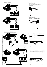
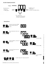
Applicative examples
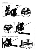
Fitted with standard jointed transmission-arm.
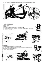
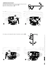
Fitted with the STYLO-BD straight transmission-arm and slide rail.
GENERAL INSTALLATION INDICATIONS
⚠
Only skilled, qualified staff must install this product.
Preliminary checks
⚠
Before beginning, do the following:
• check that the gate structure is sturdy enough, the hinges work efficiently and that there is no friction between the fixed and moving parts;
• if ground stops are not, or cannot be, fitted, use the supplied mechanical stops;
• make sure that the point where the gearmotor is fastened is protected from any impacts and that the anchoring surface is solid enough;
• make sure you have set up a suitable dual pole cut off device along the power supply that is compliant with the installation rules. It should
completely cut off the power supply according to category III surcharge conditions (that is, with minimum contact openings of 3 mm);
•
make sure that any connections inside the container (ones that ensure continuity to the protection circuit) are fitted with additional insulation
with respect to those of other electrical parts inside:
set up suitable tubes and conduits for the electric cables to pass through, making sure they are protected from any mechanical damage
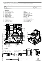
Tools and materials
Make sure you have all the tools and materials you will need for installing in total safety and in compliance with applicable regulations. The figure
shows some of the equipment installers will need.
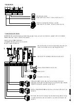
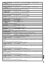
Cable types and minimum thicknesses
Connection
Tipo cavo
Cable length
1 < 15 m
Cable length
15 < 30 m
Control panel power supply 230 V AC
H05RN-F
3G x 1,5 mm
2
3G x 2,5 mm
2
Motor/encoder power supply 24 V DC
FROR CEI 20-22
CEI EN
50267-2-1
3 x 1,5 mm
2
3 x 2,5 mm
2
Flashing light
2 x 0,5 mm
2
Photocell transmitters
2 x 0,5 mm
2
Photocell receivers
4 x 0,5 mm
2
Command and safety device
2 x 0,5 mm
2
Antenna
the RG58 antenna
max 10 m
Came Remote Protocol (CRP)
UTP CAT5
max 1000 m
If cable lengths diff er from those specifi ed in the table, establish the cable sections depending on the actual power draw of the connected
devices and according to the provisions of regulation CEI EN 60204-1.
For multiple, sequential loads along the same line, the dimensions on the table need to be recalculated according to the actual power draw and
distances. For connecting products that are not contemplated in this manual, see the literature accompanying said products.
Содержание FAST 70
Страница 33: ...Operator for swing gates FA7024CB INSTALLATION MANUAL EN English FA00095 EN...
Страница 65: ...Automatisme pour portails battants FA7024CB MANUEL D INSTALLATION FR Fran ais FA00095 FR...
Страница 96: ...CAME S p A Via Martiri Della Libert 15 31030 Dosson di Casier Treviso Italy tel 39 0422 4940 fax 39 0422 4941...
Страница 97: ...A FA7024CB RU FA00095 RU...
Страница 98: ...2 2 FA00095 RU FA00095 RU 4 4 08 2017 Came S p A CAME S P A 2 5 20 1 85 1 5 EN 12453 8...
Страница 100: ...4 4 FA00095 RU FA00095 RU 4 4 08 2017 Came S p A 1 2 3 4 5 6 7 8 9 1 2 3 4 5 6 7 8 9 10 11 12...
Страница 103: ...7 7 FA00095 RU FA00095 RU 4 4 08 2017 Came S p A...
Страница 104: ...UNI 6593 14 UNI 5739 M10x14 12 UNI 6593 6 UNI 5739 M6x10 8 8 FA00095 RU FA00095 RU 4 4 08 2017 Came S p A...
Страница 105: ...UNI 5739 M6x10 UNI 6593 6 UNI 6592 12 12 9 9 FA00095 RU FA00095 RU 4 4 08 2017 Came S p A...
Страница 106: ...10 10 FA00095 RU FA00095 RU 4 4 08 2017 Came S p A...
Страница 118: ...M2 M1 M2 M1 M2 M1 M2 M1 3 a i C l i o p i c l 2 o p 2 22 22 FA00095 RU FA00095 RU 4 4 08 2017 Came S p A 3 ENTER 1 ENTER...
Страница 121: ...25 25 FA00095 RU FA00095 RU 4 4 08 2017 Came S p A...
Страница 123: ...27 27 FA00095 RU FA00095 RU 4 4 08 2017 Came S p A...
Страница 125: ...29 29 FA00095 RU FA00095 RU 4 4 08 2017 Came S p A 6...
Страница 127: ...31 31 FA00095 RU FA00095 RU 4 4 08 2017 Came S p A CAME S p A UNI EN ISO 14001...