~.,c"''''l
I_N_S_TA_LLA_T_'_O_N_O.F
ACCESSORIES
(available
upon
request)
MA7032 - Battery-powered
emergency
system
This emergency system opens the door in case of power failure.
It includes a pair of 12V (1.2Ah) batteries as
well as a circuit card that keeps the batteries charged and distributes power to the automation system.
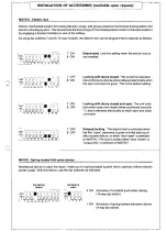
By using dip switches 9 and 10 (10-way module), the emergency system can be programmed to operate in the
following ways when the power fails:
Note: When functioning is interlocked (see p. 20), the following functions are selected equally for both auto-
mations.
9
OFF
10 ON
9 ON
10 ON
9
OFF
10 OFF
Opening
only. The doors open and remain open
until current returns to the line. The same occurs
even if the MA 7041 selector is set to -doors closed".
Closing
only. The doors closes and stays closed
(even if "door open" has been selected on MA7041)
until the mains power is restored.
Normal functioning.
The doors continue to function
until the current in the batteries drops below the
safety level, in which case they stop If the MA 7041
function selector is set to "doors closed", the doors
can only be opened by entering a command on the
2-M contact.
-----------------
~llmwHEill,,,i,
J ~
~IW~--~'
UCN.)
l~'~J
<fI ~
61
l'
I ,IJ-Wt ..
:
':-,
- ,
=
.
f••
_.,'L ......lI
.
,
:
ISOlA
_-,MlJO<'
,
1
2
3
4
5
6
7
- Mf9011.MF9111
(illI1"llfl
~
--
~
L_
_
.__ - __
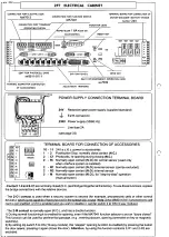
Anti-panic
device with constant
battery
control
Note: in case the MA7041 selector is not connected
and you wish to activate the anti panic function, bond
contacts 1-3 as shown in the figure.
----
-----
--.J
Setting dip switch 2 of the 10-way module to the ON position (on the
interlock system, set it on both panels) activates the constant
control
of
the battery
charge
buffer,
which during normal functioning
with 230V
power mains voltage checks the minimum charge of the 20V batteries; if
it falls below this level (on the interlock system the voltage of the batteries
of one of the two automations) the function activates a safety procedure. This procedure consists in the opening
or closing of the doors (depending on the settings of dip switches 9 and 10). Forthe interlock system, the safety
procedure (signalled by a continual flashing of LED NO.2 on the MASTER panel) causes the doors to open on
both the automatic system. After reset of the batteries, the LED goes out and the system re-starts normally after
an 'open' command.
N.B.: For sinale automation
installatio~ctivating
the battery control deactivates normal functioning (dip 9
OFF - 10 OFF).
-If function switch MA7041 is installed, make sure that the"
EMERGENCY
function has been selected (which
is indicated by a flashing yellow LED)_
- In any event, normal operation with the programmed settings will automatically resume when the mains power
is restored.
'6


