


CALIFORNIA ACCENT LIGHTING, INC.
2034 E. Lincoln Ave. #431, Anaheim, CA 92806
ph. 800.921.CALI (2254) or 714.535-7900 \ fx. 714.535.7902
[email protected] \ calilighting.com
© CALI. All rights reserved. CALI reserves the right to make changes or withdraw specifications without prior notice.
Installation Instructions
Overview
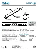
LLED
8700-OL
2 of 12
lip
LEDs
™
Symmetric Forward Phase-Control
WARNING
When using lipLEDs for any application, basic safety precautions
should always be followed to reduce the risk of fire, electric shock,
and personal injuries. lipLEDs must be installed in accordance with
the NEC or CEC as applicable.
• Do not install lipLEDs in hazardous locations or closer than 6” from
any curtain or similar combustible material.
• lipLEDs have line voltage risk of shock. Consult factory for any
malfunctions. Do not attempt to repair.
• Use lipLEDs with specified rated voltages. Do not exceed the
specified voltage for any lipLEDs luminaire.
• Ensure power is off before installation begins, during replacements,
additions, or repairs.
• Do not cover lipLEDs as the covering may cause LEDs to overheat,
melt, and even ignite the covering.
• Do not use lipLEDs if damaged, such as, broken boards, loose
connections, or frayed wire insulation. Inspect before installing.
• Do not secure lipLEDs with nails, or like means that might damage
the wiring inside. Secure it by using mounting clips.
• Do not submerge lipLEDs in liquid.
• Do not install lipLEDs on places where it is subject to
continuous flexing.
• Do not mount lipLEDs inside tanks or enclosures of any kind without
proper ventilation.
• Do not drill holes or break any barrier on lipLEDs aluminum housing,
end caps, or lens covers.
• Do not use lipLEDs extrusion as a raceway for additional wire.
Non-factory feed-through wires inside lipLEDs will void warranty.
• Ground Fault Circuit Interrupter (GFCI) protections are required
on circuits or outlets when lipLEDs is installed.
• Surge protector must be set up for electrical power system to avoid
damaging lipLEDs lighting system.
DIMMING PROTOCOL (Forward Phase Dimming)
Technical Requirements for Control Equipment
(Forward Phase Dimming)
• Electrical Characteristics - Inductive
• Special Requirements - Symmetric cycles
(VDC≤2), smooth turn off
APPLICATIONS
Accent, Decorative Lighting
VOLTAGE
120V
LAMP TYPE
LEDs
DIMMING
Triac
LENGTH
Built to Order
MOUNTING
Pendant Mount
EFFICACY
2W: 114 Lumens per foot
4W: 228 Lumens per foot
CRI
> 82
VIEWING ANGLE
120 Degrees
LED LIFE
50,000 hrs.
MAXIMUM RUN
80’ (PC-4AMP), 30’ (PC-1.6AMP)
LISTING
Dry/Damp, or Wet Location
FEATURES


