


CALIFORNIA ACCENT LIGHTING, INC.
2034 E. Lincoln Ave. #431, Anaheim, CA 92806
ph. 800.921.CALI (2254) or 714.535-7900 \ fx. 714.535.7902
[email protected] \ calilighting.com
© CALI. All rights reserved. CALI reserves the right to make changes or withdraw specifications without prior notice.
Installation Instructions
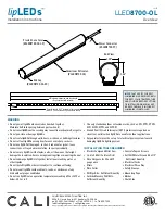
LLED
8700-OL
11 of 12
lip
LEDs
™
Surge Protector (Not Included)
PRODUCT FEATURES
The Surge Series are 3-leaded devices that protect Line-Ground, Line-
Neutral, and Neutral-Ground in accordance with IEEE / ANSI C62.41.2
guidelines. Protects against surges according to IE EE C62.41.2 C High
(10kA and 10kV). Surge current rating = 10,000 Amps using industry
standard 8/20 µSec wave. Surge Location Rated Category C3. UL
Recognized Component in the United States and Canada (UL1449). Type
4 Surge Protection Device. High temperature, flame retardant plastic
enclosure, 85°C maximum surface temperature rating. Thermally Protected
Transient Over-voltage Circuit.
PRODUCT SPECIFICATIONS
The Surge series of products are designed to be used in conjunction with
LED Drivers and fixtures to provide an additional level of protection
against powerline disturbances in industrial, commercial and residential
applications where surge protection to IEEE C62.41.2 is required.
SURGE PROTECTOR SPECIFICATIONS
MODEL
INPUT VOLTAGE
SURGE PROTECTION LEVEL
MOUNTING
ENCLOSURE
MATERIAL
INPUT LEADS
INPUT
FREQUENCY
ALS-SP
120-277V
10kV, 10kA, ANSI C62.41
Catergory C
SnapLOCK/
Footed
Polycarbonate
6”, 18AWG stranded
105 Degrees C stripped 3/8” tinned
60Hz
V(in)B
Com
Black
White
Green
Ground
Surge
LOAD
LED Driver,
or Lighting
WIRING DIAGRAM
Black
1.0” 1.52”
.26”
.26”
.41”
2.91”
1.91”
1.16”
.09”
.58”
.25”
2X ø 1.14”
V(in)B
Com
Black
White
Green
Ground
Surge
LOAD
LED Driver,
or Lighting
Black
WIRING DIAGRAM
LED Lighting
ALS-SP
Common (White)
Neutral (Black)
Green (Ground)
1.0” 1.52”
.26”
.26”
.41”
2.91”
1.91”
1.16”
.09”
.58”
.25”
2X ø 1.14”
V(in)B
Com
Black
White
Green
Ground
Surge
LOAD
LED Driver,
or Lighting
Black
WIRING DIAGRAM
LED Lighting
ALS-SP
Common (White)
Neutral (Black)
Green (Ground)
CASE DIMENSIONS
1.0” 1.52”
.26”
.26”
.41”
2.91”
1.91”
1.16”
.09”
.58”
.25”
2X ø 1.14”
V(in)B
Com
Black
White
Green
Ground
Surge
LOAD
LED Driver,
or Lighting
Black
WIRING DIAGRAM
LED Lighting
ALS-SP
Common (White)
Neutral (Black)
Green (Ground)
1.0” 1.52”
.26”
.26”
.41”
2.91”
1.91”
1.16”
.09”
.58”
.25”
2X ø 1.14”
V(in)B
Com
Black
White
Green
Ground
Surge
LOAD
LED Driver,
or Lighting
Black
WIRING DIAGRAM
LED Lighting
ALS-SP
Common (White)
Neutral (Black)
Green (Ground)


