background image


12 

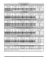
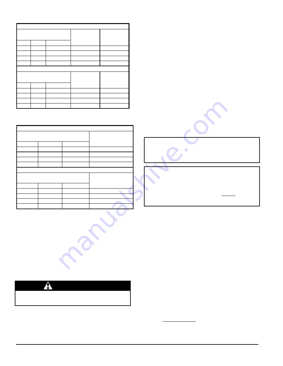
Table 5 : CFM adjustments, all modes 


CVM 105 

SW3 – ADJ (Adjustment) 

DIP Switch Positions 

POSITION 

CFM HTG. 

% increase 

or decrease 

CFM A/C 

% increase 

or decrease 

OFF 

OFF 

0% 

0% 

ON 

OFF 

+10% 

+10% 

OFF 

ON 

-10% 

-10% 

ON 

ON 

N/A 

0% 

CVM 120 

SW3 – ADJ (Adjustment) 

DIP Switch Positions 

POSITION 

CFM HTG. 

% increase 

or decrease 

CFM A/C 

% increase 

or decrease 

OFF 

OFF 

0% 

0% 

ON 

OFF 

+10% 

+10% 

OFF 

ON 

-10% 

-10% 

ON 

ON 

N/A 

0% 


Table 6 : Delay adjustments, heating mode 


CVM 105 

SW4 – Delay 

DIP Switch Positions 

POSITION 

Output 

USGPH 

OFF 

OFF 

0.75 

ON 

OFF 

0.65 

OFF 

ON 

0.50 

ON 

ON 

ALL 

CVM 120 

SW4 – Delay 

DIP Switch Positions 

POSITION 

Output 

USGPH 

OFF 

OFF 

0.85 

ON 

OFF 

1.00 

OFF 

ON 

1.10 

ON 

ON 

N/A 

 
5.  The  flame  observation  door  and  the  two  clean-out 

access  doors  (located  at  the  front  of  the  unit)  or  well 
closed; 

6.  The  burner  ‘’Reset’’  button  is  well  pushed  in  or  re-

armed; 

7.  The  preliminary  air  adjustments  on  the  burner  comply 

with the technical specifications in this manual; 

8.  The  blower  adjustments  are  appropriate  and  according 

to the specifications in this manual; 

9.  The thermostat of the room is in the heating mode and 

is set higher than the ambient temperature. 

To start the unit, turn the main electrical switch on.  


CAUTION 


Do  not  tamper  with  the  unit  or  its  controls.  Call  a 
qualified service technician. 


3.3 

PURGING THE OIL LINE 

 
1.  A  10-micron  (or  less)  oil  filter  should  be  installed  as 

closely to the burner as possible with all oil burners, but 
it  is  essential  for  burners  with  a  low  firing  rate.  We 
recommend the use of a low pressure drop oil filter with 
a capacity greater than that of the fuel pump; 

2.  On  a  new  installation,  the  air  trapped  in  the  oil  line 

leading  from  the  tank  to the nozzle must be thoroughly 
purged  in  order  to  prevent  excessive  after  drip.  The  oil 
pump  is  equipped  with  a  special  fitting  that  facilitates 
the  purging  of  any  air  between  it  and  the  tank.  The 
proper  procedure  for  performing  this  operation  is  as 
follows: 

a.  Place  a  piece  of  1/4”  diameter  clear  plastic  tubing 

over the purge fitting on the oil pump; 

b.  Start the oil burner, then open the purge fitting and 

allow  the  burner  to  run  until  the  purge  tube  is 
completely free of air bubbles; 

c. 

At  this  point  tighten  the  purge  fitting,  which  will 
allow the oil to run to the nozzle and fire the burner. 
If the purging takes longer than 15 seconds and no 
flame  has  been  established  the  burner  will  stop. 
Push the reset button on top of the Primary Control 
to restart the burner. 

For detailed information on the operation of the Primary 
Control please refer to the instructions included with the 
furnace or the burner. 

 
3.4 

COMBUSTION CHECK  


IMPORTANT:  The combustion check verification MUST be 
performed  after  the  nozzle  replacement  or  the  burner 
cleaning.  After  these  manipulations,  the  combustion 
parameters  are  necessarily  modified.  Refer  also  to  the 
burner instruction manual.  


IMPORTANT:    The  heat  exchanger  metal  surfaces  may 
have  oil  and  the  baffle  insulation  also  contains  binders. 
These  products  will  burn  or  evaporate  when  the  unit 
operates  for  the  first  time.  Because  of  this,  the  smoke 
reading may be inexact during the first minutes of operation. 
Therefore,  the  unit  must  operate  during  at least 60 minutes 
before taking any readings to adjust the combustion quality. 
Let the unit cool down before making any adjustments. 


In order to obtain optimum performance from the oil burner, 
the  following  set-up  procedures  must  be  followed  by 
referring  to  the  Technical  Specifications,  Table  5  in  this 
manual:  

1.  A test kit to measure the smoke, flue draft and over-fire 

pressure  should  be  used  in  order  to  obtain  the  proper 
air 

band 

setting.  Although  all  of  the  above 

measurements  are  required  for  optimum  set  up  and 
efficiency,  the  most  important  reading  that  must  be 
taken is the smoke number in the flue pipe, downstream 
from the regulator; 

2.  The  proper  smoke  number,  as  established  by  way  of 

engineering  tests,  is  between  0  and  1.  This  degree  of 
smoke emission is commonly referred to as a “trace”. It 
is  recommended  that  a  Bacharach  True  Spot  Smoke 
Test kit or equivalent be used; 

3.  Follow  the  next  steps  to  do  the  combustion  check 

verification:  

a.  Drill  a  minimum  proper  diameter  (about  9/32”)  test 

hole in the flue pipe, approximately 18 inches from 
the furnace breech; 

b.  From  a  cold  start,  let  the  unit  operate  for  about  5  

minutes; 

c. 

Set the burner air setting until you have between 0 
and 1 on the Bacharach Scale (or a “trace”); 

Содержание CBMAAA060120

Страница 1: ...this booklet to service the appliance and affix the booklet adjacent to the appliance after servicing C US Use of the AHRI Certified TM Mark indicates a manufacturer s participation in the program For verification of certification for individual products go to www ahridirectory org Copyright 2012 CAC BDP D 7310 W Morris St D Indianapolis IN 46231 Printed in U S A Edition Date 02 12 Manufacturer re...

Страница 2: ... Counterflow position flue pipe protection 5 Figure 2 Wiring diagram BVSO 7 Figure 3 BVSO device wiring upflow installation with vertical exhaut 8 Figure 4 BVSO device wiring upflow installation with vertical exhaust 9 Figure 5 BVSO device wiring upflow installation with horizontal exhaust 9 Figure 6 BVSO device wiring horizontal installation with horizontal exhaust 9 Figure 7 BVSO device wiring h...

Страница 3: ... applicable are CSA B139 Installation Code for Oil Burning Equipment ANSI NFPA 31 Installation of Oil Burning Equipment ANSI NFPA 90B Warm Air Heating and Air Conditioning Systems ANSI NFPA 211 Chimneys Fireplaces Vents and Solid Fuel Burning Appliances ANSI NFPA 70 National Electrical Code CSA C22 2 No 3 Canadian Electrical Code Only the latest issues of the above codes should be used and are ava...

Страница 4: ...cked to determine that it is the correct type and size m Install correct filter type and size n Unit MUST be installed so that electrical components are protected from direct contact with water 2 3 SAFETY RULES Your unit is built to provide many years of safe and dependable service provided it is properly installed and maintained However abuse and or improper use can shorten the life of the unit a...

Страница 5: ... furnace in all positions are specified in Tables 7 and 8 The furnace should be located as closely as possible to the chimney or vent in order to keep vent connections short and direct The furnace should also be located near the centre of the air distribution system 2 4 1 Air for combustion and ventilation This furnace should be installed in a location in which the facilities for ventilation permi...

Страница 6: ... on this furnace for a bottom return air duct Knockouts are provided in the floor of the furnace to facilitate the cut out requirement for the air filter rack and return ductwork We recommend the use of this opening for horizontal and counterflow installations The following recommendations should be followed when installing ductwork a Install locking type dampers in all branches of the individual ...

Страница 7: ... pipes should be supported using the proper clamps and or straps These supports should be installed at least every 4 feet e All horizontal runs of pipe should have at least 20 mm of upward slope per 1 m 1 4 per 1 f All runs of pipe should be as short as possible with as few turns as possible g Seams should be tightly joined and checked for leaks h The flue pipe must not extend into the chimney but...

Страница 8: ...e to follow this caution may result in personal injury Sheet metal parts may have sharp edges or burrs Use care and wear appropriate protective clothing safety glasses and gloves when handling parts and servicing furnaces Figure 3 Blocked vent shut off device wiring upflow installation with vertical exhaut 2 4 6 Oil burner This furnace is supplied with a high pressure atomizing retention head type...

Страница 9: ...personal injury if an electrical fault should occur A green ground screw is provided in the control box for this connection The appliance must be installed in accordance with the current ANSI NFPA 70 National Electrical Code CSA C22 1 Canadian Electrical Code Part 1 and or local codes The control system depends on the correct polarity of the power supply Connect HOT wire H and NEUTRAL wire N as sh...

Страница 10: ...w sensor turns on the electronic air cleaner when the furnace blower is operating Humidifier Humidistat A 24 VAC signal can be connected sourced from the W and C terminals on the electronic control board or a 120 VAC signal from the HUM 120 VAC or N terminals when a heat source must be used Figure 10 24 VAC Oil Furnace Wiring with Heat Pump Dehumidification capability with standard Humidistat Dehu...

Страница 11: ...the flue pipe must exit the cabinet through one of the side panel openings as above then extended up the side of the furnace Ensure that adequate clearances to combustibles are observed It may be necessary to install a sheet metal shield on an adjacent wall to prevent any possibility of a fire hazard 3 Remove the burner by unscrewing the mounting nuts Avoid putting undue strain on burner wiring It...

Страница 12: ...burner to run until the purge tube is completely free of air bubbles c At this point tighten the purge fitting which will allow the oil to run to the nozzle and fire the burner If the purging takes longer than 15 seconds and no flame has been established the burner will stop Push the reset button on top of the Primary Control to restart the burner For detailed information on the operation of the P...

Страница 13: ...t 13 of nominal heating for a period equivalent to the Pre Run Delay Refer to Tables 8 and 9 3 The solenoid valve opens and a flame is established A short time after that the ignition transformer ceases sparking 4 After the Pre Run Delay the blower slightly increases its speed for a period of time equivalent to the Short Run Delay Refer to Tables 8 and 9 5 After the Short Run Delay the blower incr...

Страница 14: ...rmine whether cleaning or replacement of parts is required If cleaning is necessary the following steps should be taken 1 Turn OFF all utilities upstream from the furnace 2 Disconnect the flue pipe only with chimney venting and rigid flue pipe 3 Remove the breech plate 4 Remove the radiator baffle 5 Disconnect the oil line and remove the oil burner from the furnace 6 Open the two cleanout doors lo...

Страница 15: ...r and remove any build up or obstruction inside the heat transfer tube 6 Re mount lock and fasten the control box with the 2 screws removed in step 3 7 Re attach the assembly cover with the screws removed in step 1 8 Re establish power to the appliance 5 0 FURNACE INFORMATION Model Serial number Furnace installation date Service telephone Day Night Dealer name and address START UP RESULTS Nozzle P...

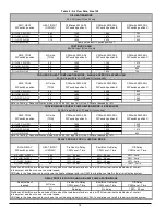
Страница 16: ...Motor HP Blow er w heel size in Filter quantity and size Overall dimensions w idth x depth x height Supply air opening w idth x depth Return air opening depth x height w ith factory filter rack Filter size Shipping w eight Air conditioning maximumoutput tons at 0 5 SP INPUT OUTPUT ADJUSTMENT see information below Pump pressure can be increased up to 180 PSIG 200 PSIG w ith Beckett burner at 1 10 U...

Страница 17: ...30 sec 38 3 min B 1 ON 2 OFF 0 65 13 45 sec 19 60 sec 38 3 min C 1 OFF 2 ON 0 50 13 60 sec 13 60 sec 38 3 min D 1 ON 2 ON All 13 30 sec 100 0 sec 100 2 min No adjustment required A C size PreRun On Delay CFM Level Time ShortRun On Delay CFM Level Time Off Delay CFM Level Time All 13 30 sec 75 2 5 min 50 3 min DELAY PROFILE FOR COOLING OR HEAT PUMP HEATING MODE PreRun and ShortRun are the periods o...

Страница 18: ...5 13 45 sec 44 30 sec 38 3 min B 1 ON 2 OFF 1 00 13 30 sec 44 30 sec 38 3 min C 1 OFF 2 ON 1 10 13 30 sec 50 30 sec 38 3 min D 1 ON 2 ON All 13 30 sec 100 0 sec 100 2 min No adjustment required A C size PreRun On Delay CFM Level Time ShortRun On Delay CFM Level Time Off Delay CFM Level Time All No delay No delay 100 90 sec PreRun and ShortRun are the periods of time when the the blower starts at v...

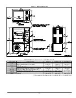
Страница 19: ... 2 54 cm 1 Ø FURNACE OR PLENUM 5 08 cm 2 5 08 cm 2 5 08 cm 2 HORIZONTAL WARM AIR DUCT WITHIN 6 ft OF FURNACE 5 08 cm 2 5 08 cm 2 7 62 cm 3 BOTTOM FURNACE COMBUSTIBLE FLOOR WITH SUB BASE Ø Ø Ø HORIZONTALLY OR BELOW FLUE PIPE 10 16 cm 4 10 16 cm 4 10 16 cm 4 VERTICALLY ABOVE FLUE PIPE 22 86 cm 9 22 86 cm 9 22 86 cm 9 FRONT FURNACE 20 32 cm 8 20 32 cm 8 60 96 cm 24 SIDES TOP FLUE PIPE When used with ...

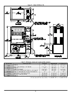
Страница 20: ...UCT WITHIN 6 ft OF FURNACE 5 08 cm 2 5 08 cm 2 7 62 cm 3 BOTTOM FURNACE COMBUSTIBLEFLOOR WITH THE SUB BASE Ø Ø Ø HORIZONTALLY OR BELOW FLUE PIPE 10 16 cm 4 10 16 cm 4 10 16 cm 4 VERTICALLY ABOVE FLUEPIPE 22 86 cm 9 22 86 cm 9 22 86 cm 9 FRONT FURNACE 20 32 cm 8 20 32 cm 8 60 96 cm 24 SIDES TOP FLUEPIPE Figure 12 Model CVM Size 120 Table 11 Minimum clearances to combustible materials When used with...

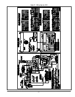
Страница 21: ...21 Figure 13 Wiring diagram CVM ...

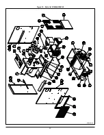
Страница 22: ...22 Figure 14 Parts list CVMAAR036105 B50003 Rev D ...

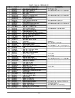
Страница 23: ... B01883 05 Blower Door Assembly Includes Door and Labels 23 B01684 Electrical Box Cover 24 B03321 01 Replacement Blower Assembly Includes Blower and Motor 25 B01687 Floor 26 A00284 High Limit Protective Shield 27 R02R002 High Limit 140F 7 STEM 28 B02111 Observation Door Assembly 29 B01680 Blower Slide Support 2 required 30 B01846 Blower Divider Panel only 31 B01679 02 Left Lateral Baffle 32 B01885...

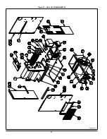
Страница 24: ...24 Figure 15 Parts list CVMAAR060120 B50004 Rev F ...

Страница 25: ...B01873 05 Blower Door Assembly Includes Door and Label 23 B01684 Electrical BOX Cover 24 B03322 02 Replacement Blower Assembly Includes Blower Motor and Capacitor 25 B01804 Floor 26 A00284 High Limit Protective Shield 27 R02R002 High Limit 140F 7 28 B02111 Observation Door Assembly 29 B01794 Blower Slide Support 2 required 30 B01795 Blower Divider Panel only 31 B01805 02 Bottom Lateral Baffle 32 B...

Страница 26: ... Utiliser l information contenue dans ce manuel afin d effectuer l entretien de l appareil Garder ce manual près de l unité pour références ultérieures C US Use of the AHRI Certified TM Mark indicates a manufacturer s participation in the program For verification of certification for individual products go to www ahridirectory org Copyright 2012 CAC BDP D 7310 W Morris St D Indianapolis IN 46231 P...

Страница 27: ...GURES Figure 1 Débit descendant protecteur de tuyau à fumée 5 Figure 2 Diagrammes électriques BVSO 8 Figure 3 Branchement BVSO installation en débit d air ascendant et évacuation verticale 9 Figure 4 Branchement BVSO installation débit ascendant et évacuation verticale 9 Figure 5 Branchement BVSO installation débit ascendant et évacuation horizontale 9 Figure 6 Branchement BVSO installation horizo...

Страница 28: ...ar une personne non qualifiée peut endommager l équipement et ou conduire à des conditions hasardeuses susceptibles d entraîner des dommages corporels IMPORTANT Toutes les exigences requises par les codes locaux et nationaux concernant l installation d équipement de chauffage au mazout les installations électriques et les raccordements de conduits doivent être respectées Certains codes émis par l ...

Страница 29: ...gne d humidité indiquant une fuite e S assurer que la fournaise dispose d une alimentation adéquate d air de combustion et de ventilation f L évacuation des gaz de combustion doit s effectuer par la cheminée g Les points énumérés à la section 3 Opération sont essentiels au fonctionnement normal et sécuritaire du système de chauffage S assurer qu ils ont tous étés bien suivis h Suivre les règlement...

Страница 30: ...un sous sol à l étage qui va être chauffé il peut être suspendu ou installé dans un vide sanitaire Dans tous les cas il doit être installé au niveau Si l appareil de chauffage central est installé dans un sous sol ou sur le sol dans un vide sanitaire par exemple il est recommandé d installer l unité sur une base en béton de 25 4 mm à 50 8 mm 1 à 2 d épaisseur Quand l appareil de chauffage central ...

Страница 31: ...exposés à l air extérieur sont munis d un retardateur continu de vapeur d eau dont le taux est d une perm ou moins et dont les ouvertures sont fermées hermétiquement ou scellées et ou b Des bandes isolantes ont été ajoutées aux portes et fenêtres utilisées et ou c Du calfeutrant ou du scellant ont été appliqués où il y avait infiltration d air comme autour des portes et fenêtres entre les seuils d...

Страница 32: ...sus du serpentin de refroidissement si la climatisation est désirée 2 4 3 Instructions d évacuation cheminée L évacuation de l appareil de chauffage central devrait se faire à l extérieur en respectant les codes locaux ou les exigences des services locaux AVERTISSEMENT Pour assurer un fonctionnement sécuritaire et satisfaisant les appareils fonctionnant au mazout devraient toujours être raccordés ...

Страница 33: ...GARDE Le dispositif doit obligatoirement être installé par une agence qualifiée Le dispositif est conçu pour détecter une mauvaise évacuation des gaz de combustion lorsque le tuyau d évacuation est bouché Lors d une anomalie au niveau de l évacuation le refoulement des produits de combustion à l interrupteur thermique permet l arrêt du brûleur au mazout Le dispositif requière une remise en fonctio...

Страница 34: ...foulement installation en débit d air ascendant et évacuation verticale Figure 4 Branchement dispositif anti refoulement installation débit ascendant et évacuation verticale Figure 5 Branchement dispositif anti refoulement installation débit ascendant et évacuation horizontale DNS 1043 Rev A Utiliser les 3 attaches fournies Les fils ne doivent pas entrer en contact avec les tuyaux d évacuation ou ...

Страница 35: ... extérieur de l unité doit posséder une mise à la terre ininterrompue pour minimiser les risques de blessures corporelles si jamais un problème électrique se produisait Une vis verte de mise à la terre est incluse dans la boîte de contrôle pour effectuer cette connexion L appareil doit être installé en respectant la dernière édition ANSI NFPA 70 du Code électrique national la Section 1 du Code éle...

Страница 36: ...té de thermopompe Capacité de déshumidification La capacité de déshumidification pour les systèmes utilisant un moteur à vitesse variable est meilleure que la plupart des autres systèmes Si cette application est requise dans un système les terminaux du contrôle électronique permettent le branchement d un humidistat standard Se référer aux figures 9 et 10 pour les instructions de branchement La fou...

Страница 37: ...que décrit ci haut puis le prolonger le long du côté de l appareil de chauffage central S assurer que le dégagement des matériaux combustibles est suffisant L installation d une feuille de métal comme écran sur tout mur pourrait être requis pour réduire les risques d incendie 3 Retirer le brûleur en dévissant complètement les écrous de montage Éviter tout stress inutile au filage du brûleur Il peu...

Страница 38: ...e l interrupteur électrique principal à ON AVERTISSEMENT Ne pas altérer l unité ou ses contrôles Appelez un technicien qualifié 3 3 PURGE DE LA LIGNE DE MAZOUT 1 Un filtre au mazout 10 microns ou moins devrait être installé aussi près que possible du brûleur dans le cas de tous les brûleurs au mazout et est essentiel avec les brûleurs à faible taux d allumage Nous recommandons l utilisation d un f...

Страница 39: ... le panneau avant de l appareil de chauffage central est requise pour déterminer s il y a un blocage dans l échangeur de chaleur ou le tuyau Les valeurs des pressions sont inscrites dans le tableau 5 spécifications techniques Une pression excessive peut être causée soit par une combustion d air excessive due à une bande d air trop ouverte par un manque de tirage de fumée effet cheminée par un bloc...

Страница 40: ...DE TEMPÉRATURE Après que l appareil de chauffage central ait fonctionné durant au moins 15 minutes restreindre l entrée d air en bloquant les filtres ou en fermant les registres de retour d air et laisser l appareil de chauffage central s éteindre en limite élevée Le brûleur va s éteindre OFF et le ventilateur principal devrait continuer à fonctionner Enlever la restriction et le brûleur devrait s...

Страница 41: ...ur effectuer la réinstallation électrique de l unité AVERTISSEMENT Assurez vous que le ventilateur est adéquatement soutenu quand vous le sortez des rails surtout en position horizontale ou en débit descendant afin d éviter d échapper le ventilateur et de vous blesser ou d endommager le ventilateur 4 3 NETTOYAGE DU DISPOSITIF D ARRÊT ANTI REFOULEMENT BVSO Pour un fonctionnement continu et sûr le d...

Страница 42: ... adresse du technicien de service RÉSULTAT DU TEST DE MISE EN MARCHE Gicleur Pression lb po 2 Ajustements du brûleur Bande principale Bande fine Position de la tête CO2 Indice de fumée Bacharach Température des gaz à la sortie de l unité F Température ambiante F Tirage dans la cheminée C E Tirage au dessus du feu C E Examiné par ...

Страница 43: ...matisation DONNÉES TECHNIQUES DU VENTILATEUR Moteur HP Dim de la roue du ventilateur po Quantité et dimensions des filtres Dimension hors tout larg x long x haut Dimension de l alimentation Dimension du retour Dimensions du filtre Poids à l expédition Capacité maximum en climatisation AJUSTEMENT CONSOMMATION PUISSANCE voir les informations ci dessous La pression de pompe peut être augmentée jusqu ...

Страница 44: ...8 3 min B 1 ON 2 OFF 0 65 13 45 sec 19 60 sec 38 3 min C 1 OFF 2 ON 0 50 13 60 sec 13 60 sec 38 3 min D 1 ON 2 ON Tout 13 30 sec 100 0 sec 100 2 min Pas d ajustement requis Capacité climatisation PreRun Délai On Niveau CFM Temps ShortRun Délai On Niveau CFM Temps Délai Off Niveau CFM Temps Tout 13 30 sec 75 2 5 min 50 3 min d air froid dans le système TABLEAU DE DÉLAIS POUR MODE CLIMATISATION OU C...

Страница 45: ...CFM diminuent de 15 SW 4 DÉLAI Position interrupteurs DIP Puissance Chauffage USGPH PreRun Délai ON Niveau CFM Temps ShortRun Délai ON Niveau CFM Temps Délai Off Niveau CFM Temps A 1 OFF 2 OFF 0 85 13 45 sec 44 30 sec 38 3 min B 1 ON 2 OFF 1 00 13 30 sec 44 30 sec 38 3 min C 1 OFF 2 ON 1 10 13 30 sec 50 30 sec 38 3 min D 1 ON 2 ON Tout 13 30 sec 100 0 sec 100 2 min froid dans le système Pas d ajus...

Страница 46: ... DE LA FOURNAISE 2 54 cm 1 5 08 cm 2 2 54 cm 1 ARRIÈRE FOURNAISE Ø 2 54 cm 1 Ø FOURNAISE OU PLÉNUM 5 08 cm 2 5 08 cm 2 5 08 cm 2 HORIZONTALE À LA CONDUITE PREMIERS 6 PI 5 08 cm 2 5 08 cm 2 7 62 cm 3 DESSOUS FOURNAISE PLANCHER COMBUSTIBLE AVEC BASE Ø Ø Ø HORIZONTALE OU SOUS LE TUYAU À FUMÉE 10 16 cm 4 10 16 cm 4 10 16 cm 4 VERTICALE AU DESSUS DU TUYAU À FUMÉE 22 86 cm 9 22 86 cm 9 22 86 cm 9 DEVANT...

Страница 47: ...RNAISE Ø 2 54 cm 1 Ø FOURNAISE OU PLÉNUM 5 08 cm 2 5 08 cm 2 5 08 cm 2 HORIZONTALE À LA CONDUITE PREMIERS 6 PI 5 08 cm 2 5 08 cm 2 7 62 cm 3 DESSOUS FOURNAISE PLANCHER COMBUSTIBLE AVEC BASE Ø Ø Ø HORIZONTALE OU SOUS LE TUYAU À FUMÉE 10 16 cm 4 10 16 cm 4 10 16 cm 4 VERTICALE AU DESSUS DU TUYAU À FUMÉE 22 86 cm 9 22 86 cm 9 22 86 cm 9 DEVANT FOURNAISE 20 32 cm 8 20 32 cm 8 60 96 cm 24 CÔTÉS DESSUS ...

Страница 48: ...23 Figure 13 Diagramme électrique CVM ...

Страница 49: ...24 Figure 14 Liste de pièces CVMAAR036105 B50003 Rev D ...

Страница 50: ...5 ASSPORTEDU VENTILATEUR Comprend porte et libelles 23 B01684 COUVERCLEDE LA BOITEELECTRIQUE 24 B03321 01 ASSVENTILATEUR DEREMPLACEMENT Comprend ventilateur moteur 25 B01687 PLANCHER 26 A00284 PLAQUE DEPROTECTION POUR HAUTE LIMIT 27 R02R002 HAUTELIMITE140F 7 STEM 28 B02111 ASSPORTED OBSERVATION 29 B01680 GLISSIERE DU VENTILATEUR 2 requis 30 B01846 SEPARATEUR DU VENTILATEUR Panneau seulement 31 B01...

Страница 51: ...26 Figure 15 Liste de pièces CVMAAR060120 B50004 Rev F ...

Страница 52: ...UVENTILATEUR Comprendporteetlibelles 23 B01684 COUVERCLEDE LA BOITE ELECTRIQUE 24 B03322 02 ASSVENTILATEURDEREMPLACEMENT Comprendventilateur moteur etcondensateur 25 B01804 PLANCHER 26 A00284 PLAQUE DEPROTECTIONPOURHAUTELIMITE 27 R02R002 HAUTELIMITE140F 7 28 B02111 ASSPORTED OBSERVATION 29 B01794 GLISSIERE DUVENTILATEUR 2 requis 30 B01795 SEPARATEURDUVENTILATEUR Panneauseulement 31 B01805 02 DEFLE...

Отзывы: