


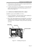


INSTALLING THE REPEATER
Page 3-4
3. Secure the module to the MMAC by tightening the knurled
knobs. Failure to firmly secure the MIM may cause improper
operation.
3.4
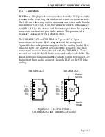
ATTACHING TRUNK CABLES TO THE REPEATER
Prior to connecting cables, check that the pinouts and maximum
cable lengths throughout the system conform to the requirements
described in Chapter 2, Installation Requirements/Specifications.
The repeater supports various media for trunk cabling. The media
connected at the Ring-In port can be different from the media
connected to Ring-Out port. Connections are made to the front
panel TPIMs.
3.5
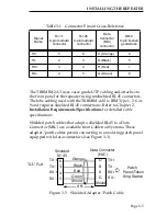
UTP AND STP LOBE CABLING
The TRRMIM-2AT and TRRMIM-4AT are equipped with twelve
TCU ports. The physical lobe connection from the concentrator
module to the token ring station does not require the use of a
crossover cable. The TCU and token ring station connectors are
wired such that the transmit pair from the concentrator module
connects to the receive pair in the station and the receive pair from
the concentrator module connects to the transmit pair in the station.
This provides the necessary signal crossover or null modem effect.
Table 3-1 provides a cross-reference of pinouts for connections that
may be encountered along the length of lobe cabling.


