


REQUIREMENTS/SPECIFICATIONS
Page 2-17
2.3.4
Connectors
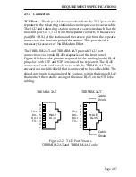
TCU Ports
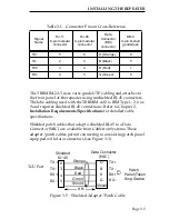
- The physical lobe connection from the TCU port on the
repeater to the token ring station does not require a crossover cable.
The TCU and token ring station connectors are wired such that the
transmit pair (TX+, TX-) from the repeater connects to the receive
pair (RX+, RX-) of the station and the receive pair from the repeater
connects to the transmit pair of the station. This provides the
necessary Crossover or Null Modem Effect.
The TRRMIM-2AT and TRRMIM-4AT provide TCU port
connections via female RJ-45 receptacles on the front panel.
Figure 2-2 shows the pinouts required for the mating (male) RJ-45
plugs for both UTP and STP versions of the repeaters. The RJ-45
connectors (male and female) used with the TRRMIM-4AT are
encased in a metallic shield that is connected to the cable shield. The
shield continuity is maintained by contacts within the female RJ-45
that contact the metallic casing of the male RJ-45 on the STP lobe
cabling.
Figure 2-2 TCU Port Pinouts
(TRRMIM-2AT and TRRMIM-4AT only)
TRRMIM-4A
MALE
RJ-45
8
7
6
5
4
3
2
1
TX+
RX–
RX+
TX–
TRRMIM-2A
MALE
RJ-45
8
7
6
5
4
3
2
1
Cable
Shield
Cable
Shield
TX+
RX–
RX+
TX–
TRRMIM-2AT
TRRMIM-4AT


