


Front and Rear Panel Descriptions
80-10200000-01
3–7
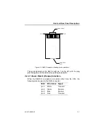
Cable Entry
point
Pin 8
Latch, at rear
Pin 1
Figure 3.3 RJ45 Connector showing pin connections
The pin assignment on the RJ45 is with pin 1 on the left, with the plug
pins facing you and the cable entry pointing downwards.
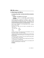
3.2.3.1 Basic Rate S (Europe) Interface
When the SBU128 is supplied in countries other than the USA, the
following pins are used in the RJ45 connector:
RJ45
Wire Colour
Signal
pin 3
White
Transmit
pin 4
Green
Receive
pin 5
Blue
Receive
pin 6
Red
Transmit
Содержание SmartSwitch SBU128
Страница 3: ...SBU128 User Manual 80 10200000 01 iii History Sheet 80 10200000 01 V1 00 Software 31 July 1998...
Страница 74: ...SBU128 User Manual 80 10200000 01 11 2 11 1 Configuration Menu...
Страница 75: ...Command Maps 80 10200000 01 11 3...
Страница 76: ...SBU128 User Manual 80 10200000 01 11 4 11 2 Operation Menu...


