


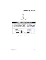


Front and Rear Panel Descriptions
80-10200000-01
3–3
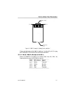
3.1.1 USER Indicators
The indicators for USER 1 reflect the signal activity on the X21 or V35
User connectors, depending which interface pcb is fitted.
TxD/T
Lights to indicate the state of Transmit Data as being ON
(SPACE).
RxD/R
Lights to indicate the state of Receive Data as being ON
(SPACE).
DTR/C
Lights to indicate the state of Data Terminal Ready as
being ON (SPACE). With the X21 interface this indicates
the state of the Control circuit.
DCD/I
Lights to indicate the state of Data Carrier Detect as being
ON (SPACE). With the X21 interface this indicates the
state of the Indicate circuit.
TxCLK/S
Lights to indicate the state of Transmit Clock as being ON
(SPACE). With the X21 interface this indicates the state of
the Signal Element Timing circuit.
RxCLK
Lights to indicate the state of Receive Clock as being ON
(SPACE). With the X21 interface this indicator is not used.
RTS
Lights to indicate the state of Request To Send as being
ON (SPACE). With the X21 interface this indicator is not
used.
CTS
Lights to indicate the state of Clear To Send as being ON
(SPACE). With the X21 interface this indicator is not used.
DSR
Lights to indicate the state of Data Set Ready as being ON
(SPACE). With the X21 interface this indicator is not used.
RI
Lights to indicate the state of Ring Indicate as being ON
(SPACE). With the X21 interface this indicator is not used.
Содержание SmartSwitch SBU128
Страница 3: ...SBU128 User Manual 80 10200000 01 iii History Sheet 80 10200000 01 V1 00 Software 31 July 1998...
Страница 74: ...SBU128 User Manual 80 10200000 01 11 2 11 1 Configuration Menu...
Страница 75: ...Command Maps 80 10200000 01 11 3...
Страница 76: ...SBU128 User Manual 80 10200000 01 11 4 11 2 Operation Menu...


