


Front and Rear Panel Descriptions
80-10200000-01
3–5
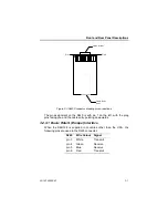
3.1.4 ISDN Indicators
These indicate the state of channels 1 and 2 on the ISDN and are:-
Indicator
Channel state
LAYER 1
Alight when the ISDN at Layer 1 (physical layer) is
active. When not alight when dialling indicates lack of
connection to the ISDN.
LAYER 2
Alight when the ISDN at Layer 2 (link layer, LAPD) is
active. This must be alight for calls to be made. If not
alight check firstly the ISDN connection, then try
dialling again. If still not alight check with your network
provider.
B1 IN USE
Lights to indicate B channel 1 on the ISDN is in use (is
carrying a call).
B2 IN USE
Lights to indicate B channel 2 on the ISDN is in use (is
carrying a call).
CONNECTED
Lights to indicate that the User port is connected to the
ISDN in backup, and data is passing over the ISDN B
channel.
3.1.5 Status Indicator
When powering up, the STATUS LED is on solid for several seconds
while the unit loads its operational software. When loaded, the STATUS
LED will flash slowly indicating unit operational status.
3.1.6 Power Indicator
This indicates the presence of internal DC power. This indicator should
always be lit when mains power is connected.
Note that if the SBU128 is not powered up, the internal pass through
relays will connect the USER port to the LINK port. This will allow
normal operation of the user’s equipment, although the ISDN backup will
not function.
Содержание SmartSwitch SBU128
Страница 3: ...SBU128 User Manual 80 10200000 01 iii History Sheet 80 10200000 01 V1 00 Software 31 July 1998...
Страница 74: ...SBU128 User Manual 80 10200000 01 11 2 11 1 Configuration Menu...
Страница 75: ...Command Maps 80 10200000 01 11 3...
Страница 76: ...SBU128 User Manual 80 10200000 01 11 4 11 2 Operation Menu...


