background image

E-5

cab Produkttechnik GmbH & Co KG

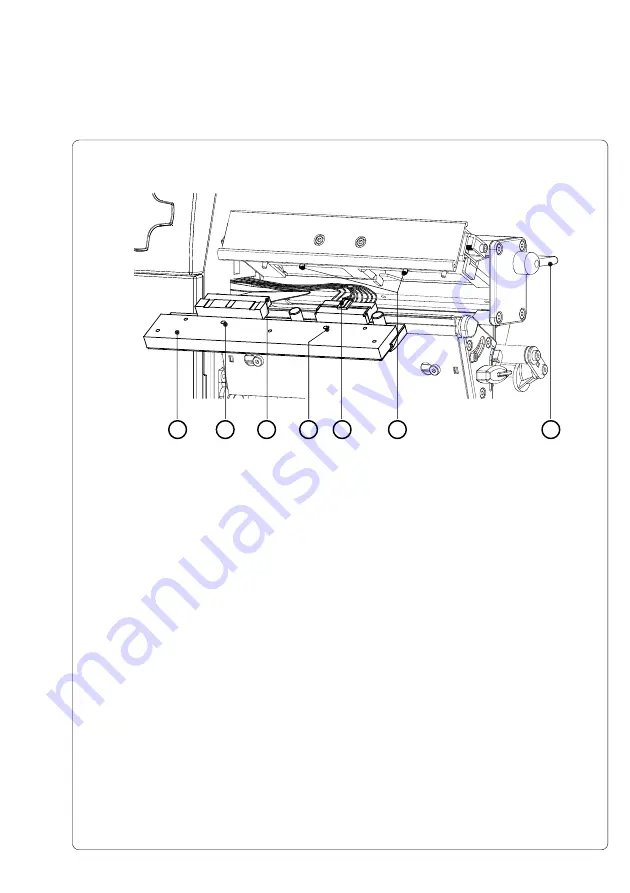
4. To lift the printhead assembly, swing the lever (

2

) clockwise until it stops.

5. Remove the printhead (

3

) from the pins (

8

) on the printhead carriage.

6. Carefully unplug the printhead (

4

) from the connectors of the printhead

cables (

6 and 7

).

7. Connect the new printhead to the cables.
8. Place the printhead into the assembly and insert the holes (

5

) onto the

pins (

8

).

9. Tighten the locking screws (

1

) by hand. Check that the printhead is

completely secured in the printhead carriage.

10. Swing the lever (

2

) again into the position shown in figure E-4.

11. Tighten the locking screws (

1

) completely.  Do not over-tighten the locking

screws (

1

).

Fig. E-5  Changing Printhead A6 (II)

2

5

5

6

3

7

8

Appendix E - Replacing Assembly Units

Содержание A4

Страница 1: ...Edition 4 03 Thermal Transfer Printer Operator s Manual ...

Страница 2: ...specifications about delivery design performance and weight are given to the best of our current knowledge and are subject to change without prior notice Gesellschaft für Computer und Automations Bausteine mbH Co KG cab Produkttechnik GmbH Co KG Postfach 19 04 D 76007 Karlsruhe Wilhelm Schickard Str 14 D 76131 Karlsruhe Telefon 49 0 721 66 26 0 Telefax 49 0 721 66 26 249 http www cabgmbh com e mai...

Страница 3: ...All rights reserved including those of the translations No part of this manual nor any translation may be reproduced or transmitted in any form or by any means for any purpose other than the purchaser s personal use without the express written permission of cab Produkttechnik GmbH Co KG Karlsruhe Edition 4 03 Printed in Germany ...

Страница 4: ...g Media Specifications 19 Transfer Ribbon 20 Software 21 2 General Safety Instructions 22 3 Unpacking 22 Delivery Contents 22 Removing the Securing Devices 23 4 Printer Component Location 24 5 Connecting the Printe 30 Connection to Power Supply 30 Connection to a Computer 31 Switch on the Printer 32 6 Control Panel 34 Use of the Control Panel 34 Structure of the Control Panel 35 Functions of the C...

Страница 5: ...nu 93 Overview 93 Label from Card 94 Print Directory 95 Copy Memory Card 96 Format Card 98 ASCII Dump Card 99 11 External Keyboard 100 Connecting the External Keyboard 100 Key Assignment 101 Special Key Functions 101 Special Characters Available with an External Keyboard 102 Appendices Appendix A Operation in Peel off Mode A 1 Components for the Peel off Mode A 1 Preliminary Tests A 2 Printer Conf...

Страница 6: ...erface Connectors B 1 Pin Assignment of the RS 232 Interface B 1 Interface Cable for RS 232 B 2 Pin Assignment of the Parallel Interface Connector B 3 Parallel Interface Cable B 3 Appendix C Error Messages Problem Solution C 1 Error Messages C 1 Recoverable Errors C 1 Non Recoverable Errors C 2 Errors during System Test C 2 List of Error Messages C 3 Problem Solution C 7 Appendix D Maintenance Cle...

Страница 7: ...o the printer In the appendices additional information such as cabling specifications error messages and problem resolution and maintenance cleaning instructions are included Please take special note of the specifications for suggested print media and the references to cleaning the printer to prevent damage poor quality printing and avoidable failures of your printer Every effort has been made in ...

Страница 8: ...thermore the printers have a keyboard interface to connect a standard keyboard as well as a bar code scanner By using a memory card it is possible to print and to enter variable data without any connection to a computer The ranging power supply 100 240VAC allows the printers to be used around the world without re configuration The operation and usage of the printers is simple and comfortable All p...

Страница 9: ...ns Printer types for internal rewinding of the labels A3 200R with 203dpi printhead and internal rewinder A3 300R with 300dpi printhead and internal rewinder A4 300R with 300dpi printhead and internal rewinder A4 600R with 600dpi printhead and internal rewinder A6 300R with 300dpi printhead and internal rewinder P Versions Printer types for peeling off the labels A3 200P with 203dpi printhead inte...

Страница 10: ...inter configuration At A4 300P A4 600P and A6 300P there is no limitation of the print speed in the peel off mode Characteristics of the Thermal Printhead CAUTION The thermal printhead is the most sensitive part of your printer Please pay special attention to the following guidelines 1 The glass cover on the printhead must not be touched with the hand Also do not use sharp objects knives screwdriv...

Страница 11: ...disadvantageous circumstances the operation of these devices may cause interference with radio or TV reception which has to be eliminated by the operator Instructions for the Lithium Battery The PCB of the printer is equipped with a Lithium battery Take necessary precautions against a possible short circuit if the battery is not fully discharged Properly remove the battery should the printer be sc...

Страница 12: ...0 75 100 mm s A6 300 2 3 4 5 6 7 8 ips 50 75 100 125 150 175 200 mm s for peel off mode On A3 the print speed is limited to maximum 4 ips 100mm s as standard Print Width A3 200 up to 4 1 in 104 mm A3 300 up to 4 25 in 108 4 mm A4 300 up to 4 15 in 105 6 mm A4 600 up to 4 15 in 105 6 mm A6 300 up to 6 4 in 162 6 mm Media Material Standard Labels and Cardboard Tags Direct Thermal Thermal Transfer an...

Страница 13: ...er up to 5 7 in 145 mm Label side out Transfer Ribbon Inkside in or out Outer Diameter up to 3 1 in 80 mm Core Diameter 1 in 25 mm Length up to 1650 in 500 m Width A3 A4 up to 4 5 in 114 mm A6 up to 6 5 in 165 mm Media Edge Sensor Distance to paper edge 16 2 3 in 4 57 5 mm Material recognition Gap sensor see through Bottom reflective sensor Electronics Processor A3 32 Bit Motorola Coldfire 64 MHz ...

Страница 14: ...0 ISO 8859 13 bis 16 Macintosh Roman DEC MSC KOI8 R Win OEM 720 UTF 8 Font Size Bitmap fonts Width and height 04 to 1 in 1 3 mm Width and height are selectable up to 10 Scaleable fonts Width and height 035 to 5 in 9 128 mm Width and height are individually changeable Font style reverse bold italic underlined outlined grey vertical Font rotation Bitmap fonts 0 90 180 270 Scaleable fonts 360 in 1 in...

Страница 15: ... A C 50 60 Hz Maximum Power Input A3 250 W A4 A6 500 W Environment Operation at 50 to 95 F 10 to 35 C at a humidity of 30 to 85 Transport at 13 to 158 F 25 to 70 C at a max humidity of 95 non condensing Storage at 41 to 104 F 5 to 40 C at a humidity of 5 to 85 Options External Media Unwinder Rewinder For operating large print jobs external unwinders and rewinders are available to handle big label ...

Страница 16: ...inter includes an option for using memory cards in order to permanently store graphics fonts or whole label formats The data can be downloaded via any of the printers data interfaces CompactFlash Type 1 cards with a maximum capacity of 64 MB are accepted Using a memory card the printer can be operated without being connected to a computer which represents a great advantage regarding the flexibilit...

Страница 17: ...ting possibilities A3 A4 and A6 are able to print on labels and continuous media with a maximum supply roll diameter of 8 2 210 mm The minimum core diameter is 1 5 38 1mm Top of form label edge detection is accomplished with a moveable photocell which is driven by the internal processor of the printer The photocell does an automatic measurement of the used material No additional adjustments are re...

Страница 18: ...void a sandpaper type effect on the printhead 3 Choose label stock which can be printed with the lowest possible thermal value The greater the thermal value required the greater wear on the printhead Additionally when the thermal value is high the time required for the printhead to heat up and cool down can have an adverse effect on the quality of print especially when a fast print speed is desire...

Страница 19: ...ckness of backing material 003 012 0 07 0 3 G Distance of the first printing position from the edge of the backing paper 08 2 1 2 5 H Distance of the label sensor from the edge of the backing paper 16 2 3 4 57 5 I Width of the perforation mark 2 5 K Height of the perforation mark 08 4 2 10 L Width of the reflective mark 2 5 M Height of the reflective mark 08 4 2 10 Label Tag Media Specifications L...

Страница 20: ... the printhead and sensors to accumulate dirt In addition with some transfer ribbons the back coating can flake or smudge leaving traces on the printhead All of these effects contribute to lowering the print quality to below desired standards Numerous tests have been conducted with a very large number of different transfer ribbons and we recommend only ribbons supplied by reputable manufacturers A...

Страница 21: ...s Printer Driver Windows Printer drivers are available for the A3 A4 and A6 printers You can get these drivers from your distributor or from the web Visit the appropriate website listed on page 2 to download the drivers The printer can be operated from any Windows Application that supports Windows Printer drivers using the Windows Printer driver The graphical user interface allows for easier creat...

Страница 22: ...head surface If the printer must be operated with the cover open extra care must be taken to avoid allowing hair jewelry clothing etc near the moving parts During the print process the printhead will become hot Use extra caution when touching the printhead Do not touch the printing surface of the printhead with you hand Any adjustments or repairs which are not described in this manual should only ...

Страница 23: ...ab Produkttechnik GmbH Co KG 1 2 3 Unpacking Fig 3 Removing the securing devices Removing the Securing Devices 1 Place the printer on a solid flat surface 2 Open the cover 3 Remove the securing devices 1 2 ...

Страница 24: ...inter Component Location Fig 4a General view 1 Warning label End of Ribbon 2 Control Panel 3 Present sensor P Versions only 4 Print mechanism 5 Internal rewinder P and R Versions only 6 Ribbon take up hub 7 Ribbon supply hub 8 Media hub 9 Media Retainer 10 Warning label End of Paper 11 Cover ...

Страница 25: ...asic Devices with printhead open 1 Printhead locking screw 2 Ribbon shield 3 Label edge sensor 4 Media feed roller 5 Tear off plate 6 Printhead support 7 Screw to adjust the printhead support 8 Printhead lever 9 Screw to adjust the ribbon shield 10 Thermal printhead 11 Media guide 12 Swing A3 Guide axle 13 Allen Key ...

Страница 26: ... 1 Printhead locking screw 2 Ribbon shield 3 Label edge sensor 4 Media feed roller 5 Rewind guide plate 6 Printhead support 7 Screw to adjust the printhead support 8 Printhead lever 9 Screw to adjust the ribbon shield 10 Thermal printhead 11 Media guide 12 Swing A3 Guide axle 13 Allen Key 4 Printer Component Location ...

Страница 27: ...inthead locking screw 2 Ribbon shield 3 Label edge sensor 4 Media feed roller 5 Dispense plate 6 Rewind assist roller 7 Locking system 8 Printhead support 9 Screw for adjusting locking system 10 Screw for adjusting printhead support 11 Allen key 12 Swing A3 Guide axle 13 Media guide 14 Thermal printhead 15 Screw to adjust the ribbon shield 16 Printhead lever ...

Страница 28: ...28 cab Produkttechnik GmbH Co KG 1 2 3 4 5 4 Printer Component Location Fig 4e Control panel 1 Display 2 Navigator pad with keys 3 Memory card LED 4 Memory card slot 5 Memory card ejection lever ...

Страница 29: ...er Component Location Fig 4f Back view 1 Slot for the additional interface card RS 422 485 ethernet or USB slave 2 Bi directional parallel interface 3 USB master interface for keyboard or scanner 4 RS 232 interface 5 Power switch 6 Power supply connector ...

Страница 30: ...y The printer is equipped with a wide range power unit 100 240V so it is possible to use the printer both with a voltage of 230V 50 Hz and with a voltage of 115V 60 Hz without making changes to the printer CAUTION Make sure the power switch 1 is in position O OFF before connecting the printer to a power supply Fig 5a Power supply Insert the power cable supplied in the accessories carton into the p...

Страница 31: ... the pin assignments for the interface connectors NOTICE For serial connection make sure the serial interface RS 232 of the printer is correctly configured to the settings of your computer see printer configuration section Connect the computer and the printer with a suitable cable and secure the cable connections with screws provided on the connectors CAUTION Make sure that all connected computers...

Страница 32: ...er switch 1 The printer will perform a short system test then display ONLINE on the front panel LCD If a hardware failure occurs during the system test the symbol and a description of the failure will be displayed on the LCD In this case the printer should be powered off and on again If the failure re occurs call for service 5 Connecting the Printer ...

Страница 33: ...33 cab Produkttechnik GmbH Co KG 5 Connecting the Printer This page is intentionally left blank ...

Страница 34: ...figured by sending printer commands from software or through direct programming The settings configured by the control panel are basic settings Parameters can be set on off for all print jobs for example Transfer print on off or the setting can be set by software for single print jobs Parameters such as Printhead position which determines the position of the print image can be set for all print jo...

Страница 35: ...ated keys The control panel display constantly provides the operator with realtime information concerning the current printer mode and label processing The function and operation of the keys depends on the current mode The available functions are marked by illuminating the valid symbols and text in the keys Fig 6a Control Panel 6 Control Panel Online 1 2 ...

Страница 36: ...FFLINE mode on Performs a label feed on Repeats the print of the last label after the previous print job has been completed Only when setup parameter Pause reprint is on on Clears internal memory of the previous print job Pause reprint is no longer available Fig 6b Navigator Pad during Printing During printing the keys on the Navigator Pad are illuminated to indicate what functions control the pri...

Страница 37: ...y System Mode PAUSE The printing process is temporarily interrupted by the operator The display shows Pause and the symbol appears Key Description Function on Continues the print job on Short press cancels the current print job Long press cancels the current print job and deletes all jobs contained in the internal memory System Mode POWERSAVE If the printer does not receive a print job or the fron...

Страница 38: ...s Continues current print job after fault correction on Short press cancels the current print job Long press cancels the current print job and deletes all jobs contained in the internal memory System Mode FAULT IRRECOVERABLE During printing a fault has occured which cannot be cleared by the operator without canceling the current print job The symbol appears on the display and the type of the fault...

Страница 39: ...herwise Test will be displayed Table 6 Structure of the Offline Menu Online Memory card Label from card Print directory Copy memory card Format card ASCII dump Card Test Short status Status print Font list Device list Printhead profile ASCII Dump Mode Test grid Label profile Setup Local settings Machine parameter Print parameter Interfaces Security Service Firmware upd Menus and options marked wit...

Страница 40: ...Move up in the menu Increase numeric values Move down in the menu Decrease numeric values Switch to a secondary menu Move the cursor to the right during numeric settings Finish a setting with confirmation of the selected settings Start of a selected test or service function Return from a secondary menu Move the cursor to the left during numeric settings Finish a setting with rejecting the selected...

Страница 41: ... the current setting of the parameter If the symbol appears in the upper line the symbol indicates that it is possible to switch between several parameters by pressing the key and the key Fig 6e Display during selection of a parameter Fig 6f Display during change of a parameter To change the current setting press the key Then the symbol is shown in the bottom line of the display indicating that it...

Страница 42: ...ere are warning labels on the media hub and on the ribbon supply hub which will be visible if the material is getting low When these warning labels are visible prepare to replace the material soon 1 Warning label End of Ribbon 2 Warning label End of Paper 4 If you do not use the printer for an extended period of time lift the printhead to avoid possible flattening of the print roller 5 If you want...

Страница 43: ...ting the optional tear off or rewind guide plate the printers also may be operated in tear off or rewind mode 2 2 3 1 7 Media Loading Fig 7b Exchange Rewind Guide Plate Tear Off Plate The exchange of the different plates can be made in a similar way as the exchange rewind guide plate tear off plate 1 Open the cover 2 Loosen the two screws 2 3 Slide the rewind guide plate 1 to the right as far as p...

Страница 44: ...revious material just swing the media retainer 11 upwards 3 Place the media roll 8 onto the media hub 9 and unwind a strip of media 4 from the media roll When operating in the rewind or peel off mode make sure that the strip is long enough to reach the internal rewinder by guiding it through the whole print mechanism and underneath of it Make sure the labels between the media hub and the print mec...

Страница 45: ...d assembly 2 by rotating the lever 7 clockwise until it stops 6 Slide the media guide ring 6 outward allowing enough clearance for the label stock s width when loaded 7 Slide the media strip underneath the swing 5 A3 axle and through the adjustable photocell assembly 3 until it comes out of the front of the printer If you are using labels that are wound in please make sure that you slide the media...

Страница 46: ...labels can be recognized by the photocell In the case of labels which have an unconventional shape ie not square or rectangular the photo cell should be positioned at the leading edge of the label Adjustment of the sensor is performed by sliding the handle 15 in and out 10 Lower the printhead by rotating the lever 7 counter clockwise until it locks 11 When the printer is operated in rewind mode co...

Страница 47: ... Then slide the media strip 4 around the rewind guide plate 16 to the internal rewind hub 13 as shown in figure 7f Slide the strip under the clamps 17 that are located on the internal rewind hub 13 Hold the internal rewind hub 13 and rotate the nut 18 counter clockwise until it is tight The media strip will now be fastened to the internal rewind hub 13 Rotate the internal rewind hub 13 counter clo...

Страница 48: ...rewind hub 13 Hold the internal rewind hub 13 and rotate the nut 18 counter clockwise until it is tight The media strip will now be fastened to the internal rewind hub 13 Rotate the internal rewind hub 13 counter clockwise to tighten the media strip 15 Loosen the screw 22 using the Allen key 24 Align the locking system 21 including the pinch roller 20 by sliding it sidewards The alignment is corre...

Страница 49: ...e Printhead Support 7 Media Loading 1 The current position of the printhead support 2 is shown by the position of the screw 3 in the elongated hole 4 2 For wide media the screw position shown in figure 7h is recommended In this position the printhead support 2 is not used 3 For narrow media it is necessary to adjust the printhead support In this case insert a second strip of a label at the outer s...

Страница 50: ...te the lever 1 clockwise until it stops 5 Slide the media guide ring 3 outward allowing enough clearance for the media s width when loaded 6 Slide the media strip through the printer as shown in figure 7i 7 Adjust the label edge sensor so that the sensor can recognize the space between the labels respectively the reflective or the perforation mark 8 Slide the media guide 6 inward until it lightly ...

Страница 51: ... guide ring 3 inward until it lightly touches the side of the media strip 10 Lower the printhead by rotating the lever 1 counter clockwise until it stops NOTICE When printing narrow label stock please activate the printhead support as described in the previous chapter ...

Страница 52: ... side of the transfer ribbon is coated with ink The inked side is generally the dull side of the transfer ribbon When the ribbon is inserted the inked side must not be placed in contact with the printhead In figure 7l the solid line represents ribbon with ink on the inner side and the broken line represents ribbon with ink on the outer side 3 Rotate the knurled knob 6 counter clockwise to clamp th...

Страница 53: ...nsfer ribbon along the path as shown in figure 7l and attach it to the cardboard core 1 using a piece of tape or a label 6 Turn the ribbon take up hub 2 counter clockwise until the ribbon is taut and without any wrinkles 7 Rotate the printhead lever 7 counter clockwise until it stops thereby locking the printhead into position Fig 7l Path of Transfer Ribbon 7 Media Loading ...

Страница 54: ...hould be done during the printing process 1 The current position is visible on the scale 3 2 To change the position rotate the screw 4 using the Allen key 5 Rotating it in the direction of will tighten the transfer ribbon the inner edge of the transfer ribbon Rotating it in the direction of will tighten the outer edge of the tranfer ribbon To eliminate the wrinkles tighten the side where the wrink...

Страница 55: ...55 cab Produkttechnik GmbH Co KG This page is intentionally left blank 7 Media Loading ...

Страница 56: ...e you can continue The numbers of the PIN can be changed by using the key and the key The position to be changed will be flashing on the display Press the key to move to the next number If the correct number is entered the Setup menu is displayed 4 The parameters are arranged in a tree like structure Pressing the key as well as the key will scroll between the secondary menus By pressing the key th...

Страница 57: ...f mode Backfeed Pause Reprint Error Reprint Width ASCII dump Interfaces Character set IEEE 1284 RS 232 RS 422 485 Ethernet Keyboard Security PIN Service The Setup menu can be protected from unauthorized access by using a PIN The parameter Demand sensor is only accessible for the P version printers The parameters in the brackets are only accessible after installing an optional device 8 Printer Conf...

Страница 58: ... time Set the printer s time Default current Setup Local settings Selection Belgie België Byjc oh Ceska republika Danmark Deutschland Ελλαρ Espana Farsi France Italia Lietuva Magyarország Nederlands Norge Polska Portugal Pmpph Schweiz Suisse Suomi Sverige Türkiye United Kingdom USA UTC 12 UTC 10 EU USA Off 31 12 2069 01 01 1970 23 59 59 00 00 00 8 Printer Configuration Local Settings 1 Switch from...

Страница 59: ...ange on the correct days to adjust for daylight savings Set date Using this parameter you can change the date in the printer s internal clock The order of data to be changed day month year is independent from the format of the date The field to be changed will be flashing on the display When printed the current date is given in the format selected based on the Country parameter It is possible to c...

Страница 60: ... dispense plate Default 0 0 mm Backfeed Delay time between removing the delay label from the peel position and the backfeed of the label Default 250 ms Limit peel off Limitation of the print speed in the spd peel off mode to 100 mm s Default A3 On A4 A6 Off Table 8c Overview of the Machine parameters Menu Setup Machine parameters Selection 9 9 0 0 9 9 9 9 9 9 9 9 9 9 9 9 500 ms 0 ms in 50 ms incre...

Страница 61: ...ing the same format on several printers and the printed image is not consistent on each printer NOTICE The value of Printhead position X cannot be greater than the difference of the printhead width and the defined label width in software A value greater than the difference will be ignored and the actual difference will be used in place For example if the printhead width is 104mm and the label widt...

Страница 62: ... the length of the additional feed can be adjusted Demand sensor Peel position This parameter allows for adjustment of the presentation position of the printed label on the dispense plate Peel position with the initial offset value of 0 causes the printed label to be peeled off from the liner leaving approximately a 1 2mm wide strip of the label still adhering to the liner The amount of label left...

Страница 63: ...urpose the speed limitation must be switched off Then the print speed can be set on all speeds up to 8 ips 200mm s for A3 200P or 6 ips 150mm s for A3 300P CAUTION When operating the A3 in peel off mode with higher speed it is strongly recommended to carry out some tests beforehand by using appropriate rolls with maximum diameter The speed limitation in the peel off mode does not affect any other ...

Страница 64: ...e amount of time the printer will wait before entering powersave mode after the last operation Debug mode The Debug mode is a tool for the firmware programmer It will assist in recognizing faults and their possible sources beyond standard error messages Table 8d Overview of the Print parameters Menu 8 Printer Configuration Parameter Meaning Heat level Basic adjustment of the heat intensity Default...

Страница 65: ...the Print parameters Menu continuation Selection Off 32 74 mm Gap sensor Bottom reflect Endless media On Off smart always On Off On Off Automatic 50mm to max print width in steps of 5mm Heat level The Heat level parameter enables the printer to adapt to possible differences in the thermal properties of the thermal printheads An adjustment has already been made in the factory If the printhead must ...

Страница 66: ... sent via Ethernet interface So the operator is already asked to prepare a new ribbon roll when the printer is still running If your printer has no Ethernet interface the diameter of the ribbon supply roll can be asked by the q r command see Programming Manual using the serial interface This method is also available if the parameter Warn level ribbon is set to Off Label sensor The printer offers t...

Страница 67: ...l is in its cut dispense position and the printer has not yet received all of the data for printing the following label Otherwise the print of the second label will be started but only completed once the first label has been removed Pause reprint When this option is enabled On it is possible to print additional labels by pressing the key after the print job has completed as long as the internal me...

Страница 68: ...to 16 Macintosh Roman DEC MCS KOI8 R Win OEM720 UTF 8 On Off 1 200 230 400 RTS CTS XON XOFF RS 422 485 Menu to configure the optional RS 422 RS 485 interface Menu is only displayed when the PCB is installed Ethernet Menu to configure the optional ethernet interface Menu is only displayed when the PCB is installed Keyboard Setting of the key assignment Menu is only displayed when an external keyboa...

Страница 69: ... affects the baud rate of the RS 422 interface and the RS 485 interface For the RS 232 interface to operate correctly it is absolutely necessary to have the computer and printer parameters set the same RS 422 485 Once the optional RS 422 RS 485 interface PCB has been installed the RS 422 485 menu appears in the interface menu The RS 422 485 menu contains the parameters necessary to configure the i...

Страница 70: ...he firmware is only possible after the PIN number is entered This allows protection against unauthorized access to certain settings and functions Menu s that are protected will display the symbol To set a code number for the first time choose the On option The first line of the display appears New PIN and the second line displays 0000 to enter the new pin With the key and the key the numbers of th...

Страница 71: ...71 cab Produkttechnik GmbH Co KG This page is intentionally left blank 8 Printer Configuration ...

Страница 72: ...he recognition of the front edge of the label in relation to the optical characteristics of the media label data sent from a computer or loaded from the memory card The test options are summarized in the Test menu of the offline menu 1 Switch from the Online mode to the Offline Menu by pressing the key 2 Press the key or the key until the Test menu is displayed Press the key to confirm the selecti...

Страница 73: ...f the Test Menu in the Offline Menu The test function Printhead profile is available for A3 only 9 Test Options Online Memory Card Test Short status Status print Font list Device list Printhead profile ASCII Dump Mode Test grid Label profile Setup Service ...

Страница 74: ... Short status option by pressing the key or the key and confirm the selection by pressing the key 4 There are ten pieces of information available using the Short status option Each piece of information is viewed seperately Use the key or the key to move between different pieces of information A4 300 Fig 9a Short status 1 The type of printer is displayed on the first line Firmware V2 82 Fig 9b Shor...

Страница 75: ...85 ethernet USB it is displayed on the ninth line Card 8 MByte Fig 9k Short status 10 If you are using a memory card the capacity of the memory card is displayed on the tenth line 5 To leave the Short status display and return to the Test menu press the key TT 64 44m Fig 9g Short status 7 The seventh line displays the length of material printed in thermal transfer mode in realtime TH 44 65m Fig 9h...

Страница 76: ...key or the key until the Test menu is displayed Press the key to confirm the selection 3 Select the Status print option by pressing the key or the key and confirm the selection by pressing the key 4 Start the printout by pressing the key 5 The Status print will be printed with the heat level and the print speed set in the Setup menu 6 To cancel the Status print press the key 7 Once the printout ha...

Страница 77: ...77 cab Produkttechnik GmbH Co KG A B D C E F 9 Test Options Fig 9l Status Print ...

Страница 78: ...rinter The font list will print continuously without sensing the label gap 1 Switch from Online mode to the Offline Menu by pressing the key 2 Press the key or the key until the Test menu is displayed Press the key to confirm the selection 3 Select the Font list option by pressing the key or the key and confirm the selection by pressing the key 4 Start the printout by pressing the key 5 The Font l...

Страница 79: ...ows No Font number for the font used in programming T command Name Name of the font as it is saved internally Type Type of the font Determines how the font is sized and what options are available when programming see the T command in the programming guide Description A detailed description of the font s name size etc ...

Страница 80: ... the label gap 1 Switch from Online mode to the Offline Menu by pressing the key 2 Press the key or the key until the Test menu is displayed Press the key to confirm the selection 3 Select the Device list option by pressing the key or the key and confirm the selection by pressing the key 4 Start the printout by pressing the key 5 The Device list is printed using the heat level and print speed set ...

Страница 81: ... number and version number of the FlashCard installed SLOT Type serial number and revision number of the interface expansion card installed USB a Type and revision number of the USB devices installed b c Speed a identifying number of the USB device b identifying number of the USB device which is connected to device a c identifying number of the device b port which is connected to device a Speed Lo...

Страница 82: ...a width of 4 7 120 mm can be used in thermal transfer mode 1 Switch from Online mode to the Offline Menu by pressing the key 2 Press the key or the key until the Test menu is displayed Press the key to confirm the selection 3 Select the option Printhead profile by pressing the key or the key and confirm the selection by pressing the key 4 Start the printout by pressing the key 5 The Printhead prof...

Страница 83: ...83 cab Produkttechnik GmbH Co KG 9 Test Options Fig 9o Printhead Profile ...

Страница 84: ... entire print width of the printer NOTICE If only small materials available then it is possible to cut the width of the printout to at least 2 in 50mm The value can be set using the parameter Width ASCII dump see chapter Setup Print Parameters 1 Switch from Online mode to the Offline Menu by pressing the key 2 Press the key or the key until the Test menu is displayed Press the key to confirm the s...

Страница 85: ...1 15 29 1D 06 06 14 0E 22 16 30 1E 07 07 15 0F 23 17 31 1F Example of ASCII Dump Mode The following shows the normal appearance of a printed label followed by the appearance of the same label when its commands are printed in ASCII Dump mode The control characters ASCII Code 00 31 as printed on ASCII Dump mode printouts are as follows Fig 9p Representation of the Control Characters in ASCII Dump Mo...

Страница 86: ...y or the key until the Test menu is displayed Press the key to confirm the selection 3 Select the option Test grid by pressing the key or the key and confirm the selection by pressing the key 4 Start the printout by pressing the key 5 The pattern shown in figure 9s will be printed The printout will repeat about every 5 seconds making it possible to make adjustments on the printer between the indiv...

Страница 87: ...87 cab Produkttechnik GmbH Co KG 9 Test Options Fig 9s Test Grid ...

Страница 88: ...ad the media to be tested in the printer 3 Switch from Online mode to the Offline Menu by pressing the key 4 Press the key or the key until the Test menu is displayed Press the key to confirm the selection 5 Select the Label profile option by pressing the key or the key and confirm the selection by pressing the key 6 The printer will carry out a media feed The sensor will measure the optical prope...

Страница 89: ...d the printed mark B Coordinates in paper feed direction where media front edges were detected C The method of media recognition gap sensor or bottom reflective sensor D The type of peripheral device connected E Settings for use by Maintenance technicians A more detailed explanation can be found in the Service Manual F Settings for use by Maintenance technicians A more detailed explanation can be ...

Страница 90: ...on the memory card Data is sent to the memory card using the printer s interface and stored on the memory card Although memory cards have non volatile memory it is recommended that you make backup copies in case the original card malfunctions or is lost Type 1 CompactFlash cards with a maximum capacity of 64 MegaByte can be used Fig 10a CompactFlash Memory Card 10 Memory Cards ...

Страница 91: ... pops out of the cover on the front panel NOTICE There are guides on the sides of the memory card which make it impossible to insert the card incorrectly Removing the Memory Card Press the eject button 3 and remove the card from the slot 2 by hand CAUTION To avoid loss of data on the memory card do not eject the memory card if the LED 1 next to the slot 2 is illuminated Fig 10b Installation of the...

Страница 92: ...he card using a FlashCard drive on a PC Writing to the Memory Card There are different methods to write formats to a memory card The most secure and practical method to write to the memory card is the printer s interface For saving a label to the memory card using direct programming place the Ms command at the beginning and end of your format Ms LBL ABC Command to save a file called ABC J H 100 0 ...

Страница 93: ...of the Memory card Menu on the Offline Menu The options Copy memory card and Format card can be protected from unauthorized access by a PIN Access to the menu shown in table 10a is only available when a memory card is installed The following sections will provide detailed information about the memory card functions listed in the table Memory Card Options in the Offline Menu Overview ...

Страница 94: ...number of labels to print Number of labels appears on the first line of the LCD On the second line 00001 appears with the first number flashing cursor 7 With the key or the key the number at the cursor position may be changed The cursor can be moved one number to the right by using the key After confirming the last number the printout will start 8 If the label was designed with operator prompted f...

Страница 95: ...om Online mode to the Offline Menu by pressing the key The Memory card menu is displayed on the LCD Press the key 2 Select the Print directory option using the key or the key 3 Press the key The directory of the card is printed 4 In the printout you can find the name of the memory card information about the data saved on the memory card the amount of space remaining on the memory card 5 After comp...

Страница 96: ...rom Online mode to the Offline Menu by pressing the key The Memory card menu is displayed on the LCD Press the key 3 Select the Copy memory card option using the key or the key Press the key 4 The Copy memory card option is displayed on the LCD with a default selection of No Change the selection to Yes using the key or the key Press the key 5 If the Copy memory card option is protected by a PIN th...

Страница 97: ...e source card yet the request Insert source will appear on the LCD 9 Remove the destination card and insert the source card again The next cycle of copying will start 10 Repeat steps 6 to 9 until all the files are copied When the printer finishes copying the files the LCD will display OK 11 Press the key to return to the Memory card menu selection list When the destination card cannot store any mo...

Страница 98: ... LCD with a default selection of No 4 Change the selection to Yes using the key or the key Press the key If the Format card option is not protected by a PIN the formatting will begin immediately 5 If the Format card option is protected by a PIN PIN 0000 appears on the display requesting input The numbers of the PIN may be changed using the key and the key The number to be changed will be flashing ...

Страница 99: ... print width of the printer 1 Switch from Online mode to the Offline Menu by pressing the key The Memory card menu will be displayed on the LCD Press the key 2 Select the ASCII dump Card option using the key or the key 3 After pressing the key the name of the first label format saved on the memory card is displayed on the LCD 4 Select the desired label format using the key or the key 5 Start the p...

Страница 100: ... external keyboard the input of variable data when using a memory card is easier Data that is typed on the keyboard will be displayed on the printer s LCD All USB keyboards with a Type A USB connector are compatible Connecting the External Keyboard Fig 11a Connecting the External Keyboard Plug the cable 2 of the keyboard 1 into the keyboard interface connector 3 located on the rear of the printer ...

Страница 101: ... the special characters cannot be displayed on the printer LCD In that case the printer will use a character which looks similar to the required character NOTICE When using a scanner the character set of the scanner has to be the same as used by the printer Special Key Functions F1 Enter the memory card directory to see labels stored on the memory card F2 Repeat the print of the last label F3 Repe...

Страница 102: ...eference to different country settings which are available with the ALT key on the external keyboard Keys of the numeric keyboard GR Deutschland SU Suomi FR France IT Italia UK United Kingdom SP España US USA DK Danmark SG Schweiz CZ Ceska republika SF Suisse BE Belgie ALT key Character Character ALT key 11 External Keyboard ...

Страница 103: ...ond character ALT Z2 For example For the letter ñ type the first character then type the second character ALT n NOTICE Use the data in table 11a to enter the Z1 character if it is not available on your keyboard Table 11b Special characters available by entering two characters one after another using the external keyboard 11 External Keyboard ...

Страница 104: ...104 cab Produkttechnik GmbH Co KG This page is intentionally left blank 11 External Keyboard ...

Страница 105: ...g The see through present sensor consisting of transmitter 1 and receiver 3 indicates the presence of a label and pauses the printing process until the label is removed After taking the label from the dispense position the next label will be printed To guarantee a maximum of reliability in the peel off mode the printer is additionally equipped with a pair of rollers 6 7 to cause the dispense tensi...

Страница 106: ...A3 When using supply rolls with a small outside diameter it is possible to increase the print speed during on demand labelling For that purpose the speed limitation has to switch off Then the print speed can be set on all possibilities until 8 ips 200mm s for A3 200P or until 6 ips 150mm s for A3 300P CAUTION When operating the A3 with higher speed it is strongly recommended to carry out prelimina...

Страница 107: ... manually from the dispense plate Locating the top of form is not necessary when the printhead was not lifted between print jobs This also applies if the printer was powered off between print jobs NOTICE To operate the present sensor the peel off mode must be activated in the software For direct programming use the P command see Programming Manual The present sensor can be used in several operatin...

Страница 108: ...el is executed if a print job is available there is no label waiting to be removed the dispense key sends the START signal This operating mode requires that there is a contact between PIN13 STA and PIN12 GND 3 Print on demand with releasing via an external control In this operating mode an external control is connected to the peripheral interface on the present sensor After removing the label the ...

Страница 109: ... line 11 12 GND Output Ground 0V 13 STA Input Start signal is active 14 RÜL Output Revers line for all output signals 15 24P Output Operating voltage 24V Si T 200mA Pin Assignment of the Peripheral Interface For use in a network environment or with a switch the present sensor is equipped with a peripheral interface to allow control of the dispensing process The interface has a 15 pin SUB D connect...

Страница 110: ...g the key will stop the print job and the printer will be reset XFEH is active when current flows between PIN2 and PIN10 PIN 4 XESP Label is in dispense position There is a label in the dispense position This signal is active if the contact between PIN4 and PIN14 is opened PIN 5 XEDG No existing print job There is no print job currently available In this state the contact between PIN5 and PIN14 is...

Страница 111: ...The signal STA is necessary to allow the Print on demand operating mode This signal is active if PIN13 is connected with PIN12 GND In this case the XSTART signal is checked PIN 14 RÜL Reverse line for all output signals PIN 15 24P Operating voltage 24V Si T 200mA The printer provides an operating voltage of 24V at PIN15 Using that voltage a trigger switch or an optical sensor can be connected to c...

Страница 112: ...s of signals result Corresponding to the operation mode input STA PIN13 must be connected with GND PIN12 or not The external device trigger switch external control to be connected must be equipped with a 15 pin SUB D connector Examples for External Circuits Fig A 4 Example with trigger switch Trigger switch Present sensor electronics 8 13 GND STA 15 24P 1 XSTART 9 RXSTART PIN1 XSTART PIN9 RXSTART ...

Страница 113: ... 24P 1 XSTART 9 RXSTART brown white black blue Sensor with npn output dependent on the used sensor Appendix A Operation in Peel off Mode Fig A 5 Example for an optical sensor with pnp output Present sensor electronics 8 13 GND STA 15 24P 1 XSTART 9 RXSTART brown white black blue dependent on the used sensor Sensor with pnp output ...

Страница 114: ... outputs are connected to one another on one side The joint line is lead to the plug connector as a RÜL signal The switch function of the outputs is to open or close the contact between the joint line RÜL and the respective output Electrical requirements Umax 42V Imax 100mA PIN4 XESP PIN5 XEDG PIN6 XDNB PIN7 XEDST PIN14 RÜL Appendix A Operation in Peel off Mode ...

Страница 115: ...B 1 RS 232 Interface Connector rear of the printer Table B 1 Pin Assignments of the RS 232 Interface Connector Pin Signal Function 1 CD Carrier Detect 2 TxD Transmit Data 3 RxD Receive Data 4 DTR Data Terminal Ready not used 5 GND Ground 6 DSR Data set ready not used 7 RTS Request to send 8 CTS Clear to send 9 RI Ring Indication not used Pin 5 Pin 1 Pin 6 Pin 9 Appendix B Pin Assignment of the Int...

Страница 116: ...facing with the printer contact the manufacturer of your computer on the pin assignments of the interface Use the pin assignment of the printer as shown in Table B 1 to obtain a compatible cable 9 pin connector 9 pin plug Fig B 2 Interface Cable with 9 pin Connector 1 1 2 2 3 3 4 4 5 5 6 6 7 7 8 8 9 9 PC Printer Appendix B Pin Assignment of the Interface Connectors ...

Страница 117: ...the manufacturer of your computer on the pin assignment of the computer s parallel interface Use the pin assignment of the printer as shown in Table B 2 to obtain a compatible cable Pin Signal Pin Signal Pin Signal Pin Signal 1 STROBE 10 ACKNLG 19 GND 28 GND 2 DATA 0 11 BUSY 20 GND 29 GND 3 DATA 1 12 PE 21 GND 30 GND 4 DATA 2 13 SLCT 22 GND 31 INIT 5 DATA 3 14 AUTOFD 23 GND 32 FAULT 6 DATA 4 15 nc...

Страница 118: ...B 4 cab Produkttechnik GmbH Co KG This page is intentionally left blank Appendix B Pin Assignment of the Interface Connectors ...

Страница 119: ...a print job errors can occur that can be recovered by the operator allowing the print job to continue from the point at which it was stopped Display The symbol appears in the display The display shows the type of error and the total amount of labels remaining for the current print job Function Keys Key Description Function flashing Continues the current print job after the error has been corrected...

Страница 120: ...t print job Long press Cancels the current print job and deletes all jobs in the internal memory Table C 2 Function of Keys in Non Recoverable Error Mode Errors during System Test When powered on the printer automatically performs an internal self test If the test is completed succesfully the printer proceeds to ONLINE mode If a hardware error occurs the symbol appears on the LCD and the type of e...

Страница 121: ...tion Switch printer off then on again If error reoccurs contact Service Make sure you are using the RTS CTS protocol to send data Replace the card Switch printer off remove media from the cutter and turn the printer on If the error message continues contact Service Otherwise check the thickness of the media and replace if necessary Switch printer off and check the media in the cutter area for poss...

Страница 122: ...ent print job Re check the data being sent Cancel the current print job Change to another font Reconfigure the printer s setup see chapter 8 If error reoccurs contact Service Switch printer off then on again If error reoccurs contact Service Cancel the current print job Reduce the amount of information on the label format Possible cause Requested file is not on the card Hardware error Hardware err...

Страница 123: ...ess the key repeatedly until printer recognizes the next label on the media Cancel the current print job Change the label size to the correct value Restart the print job Cancel the current print job Change either the software setting or the media Restart the print job Check programmimg for the S command Check programming and or database for record in question Insert new media Check the media feed ...

Страница 124: ...e Memory Card section Switch printer off then on again If error reoccurs contact Service Please note the voltage error displayed to Service personnel Repeat the write process or reformat the memory card Load a valid firmware version Possible cause Printer has received an unknown or invalid command display shows command abbreviated The interface of the computer and printer are set differently Error...

Страница 125: ...dge sensor Correct the path of the media chapter 7 Media edge sensor is dirty Clean the sensor Printer is in ASCII dump mode Cancel this mode Transfer ribbon is installed incorrectly Check to see if the inked side is facing the media chapter 7 The combination of ribbon and media is incompatible Choose a ribbon that is compatible The label height in the software is set too large Correct the setting...

Страница 126: ...rinthead appendix D The printhead support is not adjusted for the width of the media Readjust the printhead support see chapter 7 Transfer ribbon is not secured to the ribbon supply hub Tighten the knob on the ribbon supply hub see chapter 7 Problem Vertical white lines in the print image Horizontal white lines in the print image Print image is irregular or one side is lighter than the other side ...

Страница 127: ... and disconnect the printer from the outlet General Cleaning During the normal operation of the printer particles of dust and paper can accumulate inside the printer Remove these particles with a soft brush or a vacuum The cover of the printer can be cleaned with a standard cleanser CAUTION Do not use abrasive cleaners or solvents Cleaning the Print Roller Accumulations of dirt on the print roller...

Страница 128: ...egular intervals Direct Thermal Printing every media roll change Thermal Transfer Printing each ribbon change CAUTION Do not use sharp objects for cleaning the printhead Do not touch the protective layer of the printhead with your hands Clean the printhead as follows 1 Open the printhead as far as possible 2 Remove the media and ribbon from the printer 3 Clean the surface of the printhead with a c...

Страница 129: ...bel edge sensor Do not use sharp objects to clean the optical sensor 1 Remove the media from the printer 2 Press the latch 1 in the direction of the arrow in figure D 1 3 Continue pressing the latch and pull the label edge sensor 2 with the handle 4 to its outermost position CAUTION The label edge sensor cannot be removed totally There is a stop when the label edge sensor reaches the outermost pos...

Страница 130: ...D 4 cab Produkttechnik GmbH Co KG This page is intentionally left blank Appendix D Maintenance Cleaning ...

Страница 131: ... cannot be switched between printheads with 300 dpi and 600 dpi print resolution CAUTION The printhead 1 is attached and aligned on a head plate 2 Do not loosen the screws 3 that attach the printhead to the head plate Replacing the Printhead A3 A4 1 2 3 4 Fig E 1 Printhead For easy distinction between the printheads a label 4 with information about the printer type is located on the head plate A4 ...

Страница 132: ... 6 clockwise until it stops 5 Remove the printhead 1 from the pins 11 on the printhead carriage WARNING Unplug the power cord from the power source before starting CAUTION Protect the printhead against damage by electrostatic dischargement Put the printer on to a grounded conductive surface Ground yourself during printhead replacement for example using a grounded wrist strap Do not touch the conne...

Страница 133: ...inthead into the assembly and insert the holes 8 onto the pins 11 9 Tighten the locking screw 5 by hand Check that the printhead is completely secured in the printhead carriage 10 Swing the lever 6 again into the position shown in figure E 2 11 Tighten the locking screw 5 completely Do not over tighten the locking screw 5 Fig E 3 Changing Printhead A3 A4 II Appendix E Replacing Assembly Units ...

Страница 134: ...ing screws 1 using the Allen key 4 WARNING Unplug the power cord from the power source before starting CAUTION Protect the printhead against damage by electrostatic dischargement Put the printer on to a grounded conductive surface Ground yourself during printhead replacement for example using a grounded wrist strap Do not touch the connector pins of the printhead by naked hands Make sure the glass...

Страница 135: ... 7 Connect the new printhead to the cables 8 Place the printhead into the assembly and insert the holes 5 onto the pins 8 9 Tighten the locking screws 1 by hand Check that the printhead is completely secured in the printhead carriage 10 Swing the lever 2 again into the position shown in figure E 4 11 Tighten the locking screws 1 completely Do not over tighten the locking screws 1 Fig E 5 Changing ...

Страница 136: ...er at the other printer types can be made in the same way Fig E 6 Changing Print Roller and Rewind Assist Roller I 1 Lift the printhead up and swing the locking system 5 away from the rewind assist roller 4 Remove the media from the printer 2 Take the Allen key 8 loosen the screws 3 and remove the dispense plate 2 3 Remove the three screws 7 4 Remove the plate 9 and the printhead support 6 from th...

Страница 137: ...TION Before assembling the new roller check if the keys 10 13 are placed correctly in the shafts 11 12 6 Slide the new print roller or rewind assist roller onto the appropriate shaft Make sure the groove in the axle of the roller 1 4 is aligned to the key 10 13 on the shaft 11 12 7 Reinstall the plate 9 and printhead support 6 8 Tighten the screws 7 a screw first then the b screw and then the c sc...

Страница 138: ...E 8 cab Produkttechnik GmbH Co KG This page is intentionally left blank Appendix E Replacing Assembly Units ...

Страница 139: ... the key or the key until the Service menu is displayed Press the key to confirm the selection 4 The display shows Firmware upd Press the key 5 If the Firmware update option is protected by a PIN PIN 0000 will appear on the display The numbers of the PIN may be changed individually using the key and the key The number to be changed will be flashing on the display You can switch to the next number ...
Страница 140: ...ware file E EPROM could not be erased V Programming voltage too low P Programming fault NOTICE If any one of the faults described above occurs the previous firmware setting is invalid and the update has to be started again In some special cases it is possible that the printer will not return to normal operation mode after powering on after a failed firmware update In this case upload a previous fi...

Страница 141: ...63 Cutter blocked C 3 Cutter jammed C 3 Cutter stuck C 3 D Daylight saving 58f Debug mode 61 64 Device list 73 80f Direct programming 21 Direct thermal print 18 Dispense plate 22 27 48 57 60 62f A 1 Index Display 28 35ff 61 63f Documentation 7 dRAM malfunction C 3 E Error messages C 1ff Error reprint 65 67 Ethernet 16 68f F Fanfold labels 50f FAULT CORRECTABLE system mode 38 C 1 FAULT IRRECOVERABL...

Страница 142: ...ize C 5 No record found C 5 Navigator pad 28 35ff O Offline menu 36 39f 93ff Online System mode 32 36 Options15f Out of paper C 5 Out of ribbon C 5 P Parallel inteface 29 31 B 3 Pause Reprint 36 65 67 Pause system mode 37 Peel off mode 48 A 1ff Peel off operation modes A 4 Peel position 60 62 Perforation mark 19 46 Peripheral interface present sensor A 5ff Powersave mode 37 61 64 Power supply conn...

Страница 143: ... status 73ff Software 21 Speed limitation 10 60 63 A 2 Status print 73 76f Structural error C 6 Swing 25ff Switch on the printer 32 System mode FAULT CORRECTABLE 38 System mode FAULT IRRECOVERABLE 32 36 System mode PAUSE 37 System mode POWERSAVE 37 System mode PRINT 37 T Tear off mode 43ff 65 67 Tear off plate 22 25 43 Tear off position 60 62 Technical Specifications 12ff Test menu 39 72ff Test gr...

Страница 144: ...s 98 37 EU Machine Safety EN 292 2 1991 A1 1995 EC Low Voltage Regulations 73 23 EEC Data and Office Machine Safety EN 60950 1992 A1 1993 EN 60950 A2 1993 A3 1995 A4 1997 EC Electromagnetic Compatibility Regulations 89 336 EEC Threshold values for the Interference EN 55022 1998 of Data Machines Limits for harmonic current emission EN 61000 3 2 1995 A1 1998 A2 1998 A14 2000 Limits of voltage fluctu...

Отзывы: