


15
4
Replacing Assembly Units
4.5
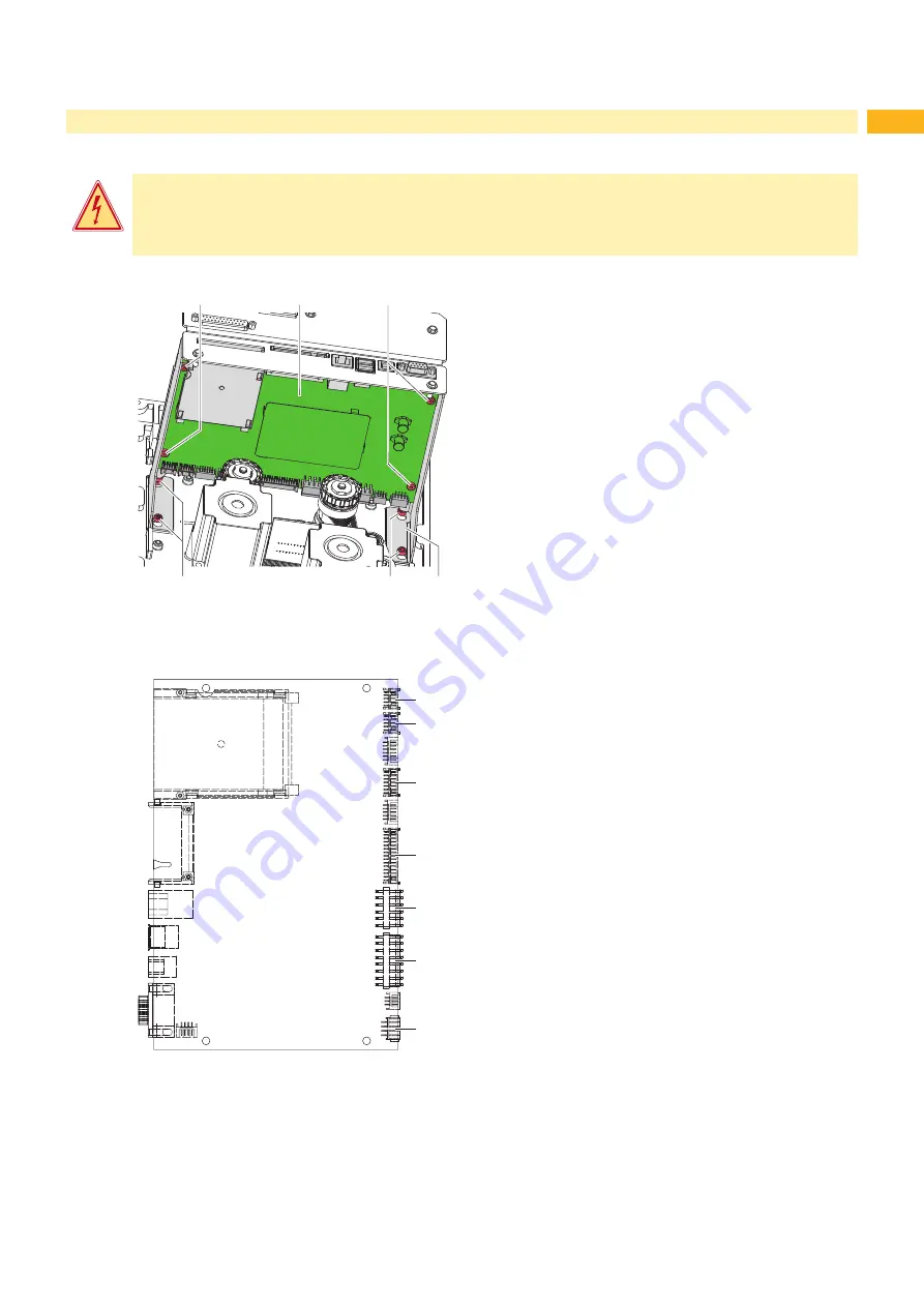
Replacing the PCB CPU
Danger!
Risk of death via electric shock!
Before opening the housing cover, disconnect the device from the mains supply and wait at lease one
minute until the power supply unit has discharged.
2
1
2
3
3
4
Removing the PCB CPU
1.
If possible, save the printer configuration to a Compact
Flash card
Configuration Manual.
2. Unplug the printer from the electrical outlet.
3. Detach all interface cables from the back of the printer.
4. Remove all memory cards from the slots.
5. Dismount cover
2.2 Cover dismount / mount
6. Loosen screws (3) and take out PCB CPU with
retainer (4).
7. Unplug all plug connections from the PCB CPU (1).
8. Loosen the four screws (2) on the PCB CPU (1).
9. Remove PCB CPU (1) .
Installing the PCB CPU
1. Fix PCB CPU (1) on the retainer with four screws (2) .
2. Insert all plug connections on the PCB CPU (1).
3. Hook in retainer with PCB CPU (1) and tighten
screws (3).
4. Mount cover.
5. Restore all interface connections on the back of the
printer.
6. Connect the power cable at the rear of the printer.
7.
Update the firmware if necessary.
8. Adjust the label sensor
Configuration Manual.
9.
Load the printer configuration from the memory card if
possible.
Otherwise, set the printer configuration via the control
panel
Configuration Manual.
5 PCB USB Hub
6 PCB Ribbon saver
7 Sensors
8 Printhead signals
9 Printhead power supply
10 Power supply unit
11 Stepper motor
Fig. 13 Replacing the PCB CPU
5
6
7
8
9
10
11
Fig. 14
Connectors on the PCB CPU
Block diagram
Содержание PX Series
Страница 1: ...Made in Germany Service Manual PX Print Module ...
Страница 35: ...35 8 Layout Diagram PCB CPU Fig 36 Layout diagram PCB CPU components side ...
Страница 36: ...36 36 8 Layout Diagram PCB CPU Fig 37 Layout diagram PCB CPU soldering side ...
Страница 38: ...38 38 This page is intentionally left blank ...


