


Service Manual
This product has passed CE certifications, including GMP Taiwan,
ISO9001, and ISO13485.
※
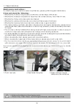
In case of any discrepancy between the illustrations and accessories in this manual
and the actual Scooter, the actual Scooter shall prevail.
※
The Company reserves the right to design and modify this scooter.
HS-928
S81201-92800