background image

DSPXmini-FM operational manual V1.2

21

Like most competent audio processors the AGC stages in the DSPXmini-FM are gated. This slows down the 

release time of the multi-band AGC when the program material drops below a certain level. This prevents noise 

suck up and gain hunting from occurring during quiet periods or lulls in the audio. The DSPXmini-FM allows 

adjusting the  gate level over a range of -20dB to -0dB. This is the level at which the program material must 

fall below for the gate to become active. The gate level control has two more options, OFF and ON. OFF is self 

explanatory and prevents the gate from having any effect. ON is often referred to in this manual as ‘forced gat-

ing’ as it has the effect of switching the gate on at all times with any level of program material. This option is 

used to bypass the AGC. 

Under gated conditions, the gain reduction will slowly move to average gain the AGC had in the recent past. 

This preserves the frequency balance of program material when multi-band AGC is gated.

Multi-band limiters

The multi-band limiter drive can be adjusted over a +/- 12dB range. Increasing the drive will increase the level of 

limiting and with it on air loudness. Above a certain level of drive no more loudness will be obtained and all that 

will happen is you will generate higher levels of IM distortion and the sound will take on a busy packed texture. 

You may also observe higher levels of high frequency noise when the band  and  drives are increased. We 

don't usually find much use for drives above +6dB but more may be required if other settings are adjusted to 

compensate. In any case, observe the peak limiter meters for a good indication of how much drive to use. We 

don't recommend more than 9dB of gain reduction especially on bands 2,  and . Gain reductions of 2-6dB are 

a good compromise between loudness and quality.

The multi-band limiters in the DSPXmini-FM are of the dual time constant variety. There is an attack and decay 

to handle the peaks and an attack and decay to handle the average level of limiting. Understanding how the two 

time constants interact is imperative if you want to make major changes to how each bands limiter reacts. We 

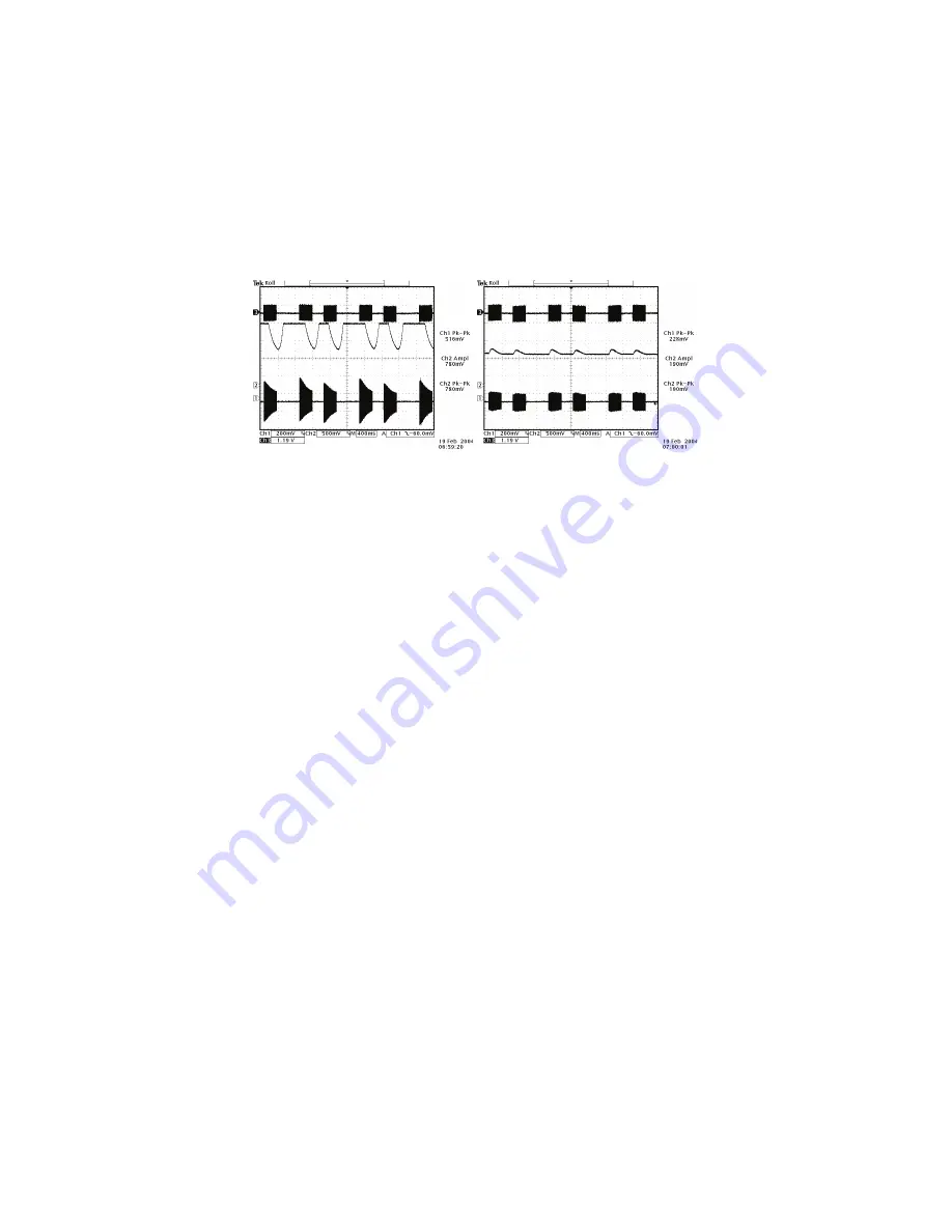
have included some scope screen captures to illustrate things a little clearer. The peak and average function can 

clearly be seen in the images.

Traditionally audio limiters have two time constants, an attack, the time is takes the limiter to respond to a signal 

above the threshold and a decay or release which is the time is takes to respond to a drop in level. In a tradi-

tional audio limiter the attack time is usually set to somewhere in the region of a few milliseconds and the decay 

time considerably longer at somewhere in the hundreds of milliseconds. This is not the most optimum solution 

because transients that last only a few milliseconds will reduce the level of the waveform for hundreds of mil-

liseconds, reducing loudness and creating audible pumping effects. 

The solution is multiple time constants where one set of time constants can be set to handle the fast peaks and 

another to handle the average level of limiting. Fast transients will release in a faster less noticeable way and 

won't punch holes in the sound in a way that single time constant limiters can. The secondary slower time con-

stant circuit will not have much effect on the audio waveform when hit with a transient because the higher attack 

time, generally in the hundreds of milliseconds will not allow a build up of energy. In the case of a sustained 

envelope of audio above the threshold the multiple time constant will attack as normal with the peak time con-

stant but the sustained energy will also charge the secondary slower circuit. When the audio energy falls away 

and the circuit goes into release the peak decay will dominate until it reaches a point where it hands over to the 

slower secondary time constant for a slower rate of decay. The illustrations show this to good effect, where tran-

sients have a fast release but multiple or sustained transients build up energy in the secondary circuit which acts 

as a platform for the peak to release to. The secondary circuit's platform can be thought of as the average level 

of limiting. Having this fast peak responding circuit ride on top of the average circuit creates many advantages, 

limiter transparency, less chance of pumping and greater loudness. By setting the time constants appropriately 

we can have the multiple time constant based detectors work as peak handling, average handling or the opti-

AGC attacking and decaying with gating disa-

bled

AGC attacking and decaying but with gating 

enabled

The effects of gating

Содержание DSPXmini-FM

Страница 1: ...DSPXmini FM Broadcast Audio Processor Operational Manual Version 1 2 www audio processor com...

Страница 2: ...udio processing 12 Source material quality 13 DSPXmini FM placement 13 The DSPXmini FM and its processing structure 14 Processing block diagram 15 The DSPXmini FM menu system 16 The Menu structure 16...

Страница 3: ...Free inspections and maintenance repair work are expressly excluded from this warranty in particular if caused by improper handling of the product by the user This also applies to defects caused by n...

Страница 4: ...ves or other appliance including amplifiers that produce heat Power Source The appliance should be connected to a power supply only of the type described in the operating instructions or as marked on...

Страница 5: ...336 EEC electromagnetic compatibility Conformity is declared to those standards EN50081 1 EN50082 1 WARNING This equipment generates uses and can radiate radio frequency energy If not installed and us...

Страница 6: ...r was the DSPX Why DSPX Like most products the concept is conceived nameless The name DSPX came about for several reasons Firstly the BW team couldn t decide on a name we liked so the concept became D...

Страница 7: ...level control circuitry 6 x 24 bit DSP s an ethernet port a trigger port an RS232 port an LCD screen and memory devices to hold the software and firmware The Processing Architecture After input select...

Страница 8: ...NEW PASSCODE 3779 U2 ROUND FACE U3 CLASSICAL 3 A SAVE PRESET UP GO U1 BASS FACE U2 ROUND FACE U3 CLASSICAL 3 A INS DEL DONE NAME PRESET U2 MY PRESET 3 UP LOAD SAVE DSPX OUTPUT PROCESS INPUT Analogue...

Страница 9: ...PXmini FM are low and or com ing from unbalanced source you might want to set the jumpers for 12dBu operation You can check the levels going in DSPXmini FM at any time by bringing up the metering scre...

Страница 10: ...tion of the multi band AGC The range shown is 21dB to 21dB in 3dB steps There is only one meter per stereo channel and the value shown is the largest gain reduction of the left and right channels Unde...

Страница 11: ...INPUT menu Apply audio and observe the input meters 5 Select the pre emphasis setting for your region input menu 75uS for USA and 50uS for Europe 6 Navigate to the STEREO menu and adjust the MPX OUTPU...

Страница 12: ...owed by limiting and then finally peak clipping Compression Compression reduces the dynamic range of the audio waveform slowly in a manner similar to a trained operator riding the gain Compression is...

Страница 13: ...for audio storage If you must use compressed audio we advise rates of 256 Kbps and higher Linear formats are always to be preferred Compressed audio formats employ frequency masking data reduction te...

Страница 14: ...ith a choice of 4 Q s This can be thought of as a simple bass parametric Xover The DSPXmini FM employs linear phase time aligned digital FIR filtering to split the audio spectrum into 4 bands while ma...

Страница 15: ...DSPXmini FM operational manual V1 2 15 4 32 7 054 0 0 0 0 33 0 02 7 0 33 0 0 54054 08 0 4 54 08 0 0 0 4 3 08 54 308MINI 02 33 2 0...

Страница 16: ...n the softkey functions are contained in the appropriate sections of this manual Menu Structure menu input INPUT SOURCE pre emphasis menu PROCESS menu enhance peaking bass GAIN peaking bass FREQ peaki...

Страница 17: ...between 1 and 10 which corresponds to 100mS to 10S on a semi exponential scale DECAY Controls the release decay rate of the AGC the time the AGC takes to respond to a decrease of input level The DECA...

Страница 18: ...N CLIPPER HARDNESS Another distortion controlling mechanism that helps to reduce IMD in the final clipper The range is 1 to 10 with 10 producing the least distortion control A setting of 10 effectivel...

Страница 19: ...ock The options are enabled and disabled More information is available in the code lock section of this manual REMOTE SOURCE This selects the seria or the NET LAN port as the remote control method The...

Страница 20: ...peak limiter stages Because of the RMS based level detectors the multi band AGC can re equalise the sound in a more natural manner than the peak limiter stages which use peak detectors As the human e...

Страница 21: ...o illustrate things a little clearer The peak and average function can clearly be seen in the images Traditionally audio limiters have two time constants an attack the time is takes the limiter to res...

Страница 22: ...eak circuit releases to The mixer The post limiters mixer in the DSPXmini FM is not strictly a mixer but a band output level control where small EQ changes can be made Be careful when making large EQ...

Страница 23: ...range has been limited to restrict the amount of control preventing pumping and a loss of loudness which would undo what we want to use the clipper for which is gaining loudness You may not notice th...

Страница 24: ...eed up the release times making them faster While it is possible to create a strange response in the multi band AGC it is hard to produce distortion because whatever gets through the AGC is dealt with...

Страница 25: ...nd 1 and band 2 average attack time so that the peak time constant dominates the control signal providing faster control Bass clipper Increase the bass clip level WE SUGGEST ONLY SMALL MODIFICATIONS F...

Страница 26: ...tortion controlled HF clipper WE SUGGEST ONLY SMALL MODIFICATIONS FROM FACTORY PRESET SETTINGS IF YOU ARE MODIFYING LOTS OF THE PARAMETERS IF YOU ARE ADJUSTING ONLY A COUPLE FROM THE ABOVE SUGGESTIONS...

Страница 27: ...re happy with the name you press the DONE soft key to save the preset to the DSPXmini FM s memory For speed saving the current settings to the same active preset is as simple as pushing the same butto...

Страница 28: ...BASS A preset for competitive stations who want loudness and more of a signature sound with lots of bass This presets packs a maximum amount of bass while still remaining loud F6 HOT Very loud presets...

Страница 29: ...int in time so you will need to select which one of the two remote control methods you wish to use by selecting the appro priate option from the remote source parameter which is contained in the syste...

Страница 30: ...AN port to control the DSPXmini FM follow the steps below 1 Connect a cat 5 cable to the RJ45 port on the DSPXmini FM and plug this into your network hub switch A Xover cable can be used to connect di...

Страница 31: ...t of the application you have the menu preset toggle buttons These change the contents of the left hand window from the DSPXmini FM menu tree to the preset list The top right of the application contai...

Страница 32: ...efault preset Unlikely but possible Various preset operations are possible including changing the default preset saving a preset to a user preset location changing the name as well as PC file operatio...

Страница 33: ...arts Each has three parameters The left hand box contains the name of the preset that you want this daypart to switch to This box also has the ability to turn the daypart OFF by clicking down on the a...

Страница 34: ...changes you have made to the processing against the saved preset When you load a preset the buttons should be greyed out but as soon as you make any processing changes these buttons will become active...

Страница 35: ...ger pins When the trigger pins are connected to the earth return pin they will change the currently active preset to the user preset triggered by that pin If more than one pin is pulled low at the sam...

Страница 36: ...entered with the use of the rotary encoder and the GO soft key can be pressed to confirm entry and proceed If unsuccessful you will be required to try again If successful the DSPXmini FM will allow yo...

Страница 37: ...gers when the daypart start time matches the system clock You can also set the start time trigger of each daypart and set the length that the daypart shall be the time the trigger shall remain in forc...

Страница 38: ...mono from left mono from right or mono from sum Sampling Rate 32 44 1 48 88 2 or 96 kHz automatically selected Connector XLR female Pin 1 chassis ground pins 2 and 3 transformer balanced and floating...

Страница 39: ...19200 kbps Ethernet Port 10 Mbit sec on RJ45 female connector Remote Control trigger port DB9 opto isolated and floating Eight pull low inputs Other Voltage 100 240 VAC 50 60 Hz 35 VA Connector IEC De...

Отзывы: