Appendix B
Electrical
Drawings
Page B-7
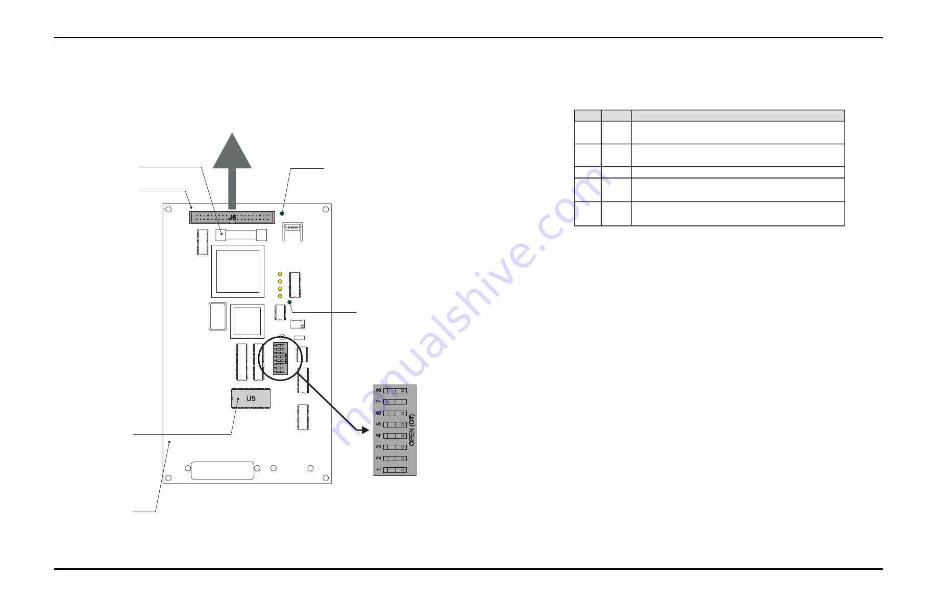
Figure B-7:
Tabber CPU Board DIP Switches Setting.
L1
L2
L3
L4
POWER
System Support Interface Cable
P/N 606311A
Connects to Tabber Interface Board
P/N 9101133
Power LED will turn ON when power is applied to
the board and the fuse is OK.
F1
Fuse, 12VDC @ 1A, AGC1
P/N 646003
Serial Number Location
Tabber Chip (U5)
EPROM
P/N 9101944
RUN
Run LED is ON when processor is operating.
The LED will blink if there is a problem with
the processor.
RV1
NOTE
: DIP switches configuration shown are set for BK730 Tabber.
See Table A for other configurations.
Off
On
Off
On
Off
On
Off
Off
On
Setting
Stop output relay de-energized (for BK7IB base)
Stop Output Relay Energized (for standard BK730 base)
Standard Encoder, 600 DPI (BK730 Tabber)
Standard Encoder, 660 DPI (for BK7IB base)
Future Use
For Rev E Board
For Rev A-D Board
Reserved for Factory Reset
Factory Reset (all other DIP switches must be Off)
Function
1
2
3 - 6
7
8
DIP
Table A - Tabber CPU Board Dip Switch Assignments
REV E
Revision Number Location
To reprogram the board:
1. Turn the base power off.
2. Switch DIP 8 ON and all other DIP switches OFF.
3. Turn the base power on and wait at least 60 seconds.
4. Turn the base power off.
5. Return the DIP switch settings to normal (Reference Table A).
The board is now reprogrammed.
Buskro Ltd.
BK731 Labeler
Содержание BK731
Страница 1: ...BK731 Labeler Part No 9100619 User s Guide V1 0 ...
Страница 5: ...General Information Chapter 1 1 0 General Information Buskro Ltd BK731 Labeler ...
Страница 12: ...BK731 Options Chapter 2 2 0 BK731 Options Buskro Ltd BK731 Labeler ...
Страница 23: ...Mechanical Adjustments Chapter 3 3 0 Mechanical Adjustments Buskro Ltd BK731 Labeler ...
Страница 31: ...User Interface Chapter 4 4 0 User Interface Buskro Ltd BK731 Labeler ...


