5 | Installation
20 / 36
0870557375_NC2000B_VR_Ex_A0002_IM_en
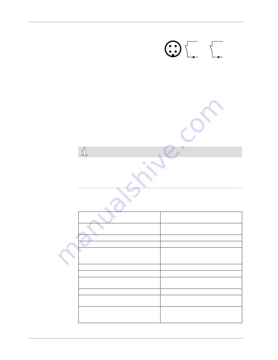
5.7.3 Wiring Diagram Level Switch
Part no.:
0652 556 531
Supplier reference:
Endress&Hauser FTL50/FEL58
Maintenance procedure:
Procedure F [
►
29]
Connector:
M12x1, 4-pin
P&ID position:
LS-/0201 & LS+/0202
Electrical data:
Ui = 16 VDC ; Ii = 52 mA ; Pi = 0.17 W ; Ci
= 0 nF
1
2
4
3
4 -
1 +
L
2 -
1 +
L
I
I
1 = Brown ; 4 = Black
1 = Brown ; 2 = White
Switching element function:
NAMUR
Contact:
Normally closed
Switch point:
L
trip
= LS-/0201
►
pin 1 + 4
►
low level “stop the machine”
L
trip
= LS+/0202
►
pin 1 + 2
►
high level “stop the machine”
I > 2.2 mA
►
Level: OK
I < 1 mA
►
Level: not OK
►
“stop the machine”
NOTE
Prior to starting the machine, both level switched (LSA-/0201 and LSA+/0202) must be
checked.
The maximum time between two level checks is 24 hours.
The level switch outputs (LSA-/0201 and LSA+/0202) are to be ignored during the cyc-
lic operation oft he machine.
5.8 Operating Parameters
• Make sure that the cooling liquid complies with the following requirements:
Continuous cooling liquid injection rate*
(INJ)
2 … 6.5 l/min
Minimum constant cooling liquid injection
rate (INJ)
2 l/min
Cooling liquid flow rate (CLI)
18 l/min
Ambient temperature range (standard)
-20 … 40 °C
Ambient temperature range (high tempera-
ture version, refer to pump nameplate)
Specific motors
-20 … 60 °C
Cooling liquid supply temperature
10 … 40 °C
Max. allowable gas inlet temperature
70 °C
Max. exhaust gas temperature (TSA
+/0102)
80 °C
Recommended exhaust gas temperature
60 °C
Max. cooling liquid outlet temperature
(TSA+/0101)
55 °C
Max. operational temperature difference
between cooling jacket and exhaust gas
outlet
70 °C
Содержание COBRA ATEX
Страница 35: ...Note...


