background image

39

TECHNICAL PASSPORT. INSTALLATION and OPERATION MANUAL

TECHNICAL PASSPORT. INSTALLATION and OPERATION MANUAL

CAUTION!  You  must  use  gas 

analyzer when setting the burner.

The  Pell  pellet  burner  is  equipped  with 

two-step  output  adjustment  and  their 

setting  depends  on  the  boiler  and  heat 

requirements of the heating installation.

11.1. Calibration of auger fuel feed rate.

The  auger  fuel  feed  rate  changes 

depending on the density and size of the 

fuel  used.  Therefore  it  is  necessary  to 

calibrate the main auger every time you 

change the type of the fuel used.

CAUTION! It is recommended to 

use  the  same  fuel  throughout 

the heating season.

Once you have installed the pellet auger 

according  to  the  instructions  in  the 

manual, fill the hopper with fuel (pellets). 

Connect  the  power  supply  of  the  pellet 

auger  directly  to  the  power  mains.  The 

auger  is  now  in  operation.  Wait  about 

15-20

  minutes  for  the  pellet  auger  to 

fill  with  pellets.  The  auger  is  filled  with 

pellets when pellets begin to fall from the 

T-branch of the auger at the point where 

the auger hose is attached. 

Filling  of  the  pellet  auger  is  necessary 

when  the  fuel  in  the  hopper  has  been 

depleted or when fuel has been changed.

Once  you  have  ensured  that  the  pellet 

auger  has  been  filled,  take  an  empty 

plastic  bag  and  fixed  it  securely  on  the 

pellet  auger,  at  the  place  of  the  auger 

hose. Reconnect the auger to the power 

socket and measure the amount of pellets 

collected in the bag over a period of 15 

minutes  using  scales/weighing  scale. 

(In  our  example,  the  amount  of  pellets 

collected  in  the  bag  over  a 

15

-minute 

period  is 

7875

  grams.  (

900  sec

).  We 

then  divide 

7875

  by 

900

  and  get 

8.75


grams  of  pellets  per  1  second.  Repeat 

the  measurement  in  order  to  obtain 

conclusive results.

11.2. Burner output adjustment.

In  the  burner  output  settings  menu  you 

can adjust the running time of the main 

auger  (

Feed

);  main  running  interval 

(

Cycle

) and fan output (

Fan

). 

Example  for  Pell  25  model:

  we  select 

mode Cycle = 

20 sec.

 The heating value of 

your  fuel  is 

4.8  kWh/kg

.  (manufacturers 

indicate the heating value of the fuel on 

the packing – take it from there). We then 

employ the following formula to calculate 

the  number  of  seconds  for  setting  the 

operation of the main auger for these 20 

seconds.

t

FEED

 = 25 000/(4.8 x 180 x 8.75)

 hence

t

FEED  

=


3.3 sec., 

where 

25 000

 is the desired 

output of the burner in Watts (W), 

4.8

 is 

the heating value of the fuel in kWh/kg

180

 is the number of burning cycles per 

1  hour, 

8.75

  is  the  amount  of  pellets  in 

grams fed by the auger per 1 second.

This  way  the  output  mode  can  be 

changed and instead the number 

25 000


–  25kW

,  we  input  the  desired  kilowatts 

(40 kW=40000 W, 70 kW=70000 W etc.).


Take  also  note  of  the  fuel  heating  value 

which  would  change  the  value  for  the 

feed and the burner output.

Using  the  above  procedure,  you  can 

set any of the two output modes of the 

burner.

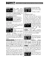
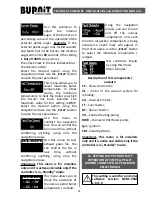
Mode 

:  Max  Power  Setup

  -  It  is 

indicated by two flames.

Pellet  auger  running  time  (Feed)

 – 

3.3 

sec. (25kW)

Main combustion cycle (Cycle)

 – 

20 sec.


(recommended)

Содержание PelleBurn 15

Страница 1: ...TECHNICAL PASSPORT INSTALLATION and OPERATION MANUAL FOR AUTHORIZED INSTALLER SERVICE SHOP PELLET BURNING BOILER PelleBurn series Version i0 8 3 EN...

Страница 2: ...2 TECHNICAL PASSPORT INSTALLATION and OPERATION MANUAL TE TECHNICAL PASSPORT INSTALLATION and OPERATION MANUAL TE...

Страница 3: ...ger and fuel hopper 15 7 3 Connecting the boiler to the mains power supply 15 7 4 Connecting the boiler to the heating installation 20 7 5 Connecting diagrams 22 8 FILLING THE HEATING INSTALLATION 26...

Страница 4: ...ing installation and operation the country specific requirements and regulations must be observed Local construction regulations on installation air supply and exhaust gas extraction as well as chimne...

Страница 5: ...unning boiler inside It is mandatory to assure a backup power generator of corresponding rated power see table 1 Customer must undergo boiler operation maintenance training by authorized installer ser...

Страница 6: ...ic tiles baked clay solutions plaster free of organic additives Class B hardly flammable Gypsum board panels basalt fiber needled felt fiberglass board AKUMIN Izomin Rajolit Lignos Velox Heraklit Clas...

Страница 7: ...Burn boiler achieves efficiency rate of as much as 91 2 2 Design of pellet burner Pell Theburnerismadeofhigh qualitystainless steel able to withstand temperatures of up to 1150 The burner must be inst...

Страница 8: ...oad etc the overload is borne by the electrical fuse fitted on the main control panel of the burner 10 Power interruption Innovative controller Incaseofpowerinterruption all parameter settings are sto...

Страница 9: ...waste wood Wood pellets are produced in hammer mills or wood pellet plants Advantages of wood pellets Convenient storage Pellet bags can be stored on a small area in a dry garage basement service room...

Страница 10: ...on about the storage conditions We recommend to use pellets with size of 6 8 mm Density 600 750 kg m3 heating value 4 7 5 5 kWh kg Ash content less than 1 and moisture content up to 8 EN 14961 2 2011...

Страница 11: ...Lead content mg kg 2 10 10 10 Nickel content mg kg 2 10 10 10 Zinc content mg kg 2 100 100 100 1 not more than 1 of the pellets may be longer than 40 mm max length 45 mm 2 dry weight 3 particles 3 15...

Страница 12: ...r is placed must be removed by unscrewing the bolted connections using flat ring wrench S13 PelleBurn 15 25 40 A1 mm Pellet boiler burner and pallet 710 710 810 A2 mm Auger box 120 120 120 A3 mm Fuel...

Страница 13: ...continuous access of air necessary to maintain combustion Boilers must not be placed in inhabitable rooms All boiler rooms must have correctly calculated vent depending on the boiler output The vent m...

Страница 14: ...inside The inner section of the flue outlet must not be greater than the effective section of the chimney and must not narrow Avoid using elbow joints The chimney cleaning opening has to be in its low...

Страница 15: ...4 Auger 5 Fuel Hopper FH Diagram 6 Pellet burner Pell and Fuel Hopper connected to pellet boiler PelleBurn 7 3 Connecting the boiler to the mains power supply Such connection must be performed by a t...

Страница 16: ...ANUAL TE TECHNICAL PASSPORT INSTALLATION and OPERATION MANUAL TE L N N L L N L N N L N L Buffer bottom sensor DHW Sensor DHW Pump 220 V CH Pump 220 V Room termostat Power supply 220V 50Hz Buffer top s...

Страница 17: ...001 002 004 005 006 007 008 009 010 011 012 013 014 015 018 019 I01 I02 I03 I04 I05 I06 I07 I08 I09 I10 I11 I12 I13 I14 I15 I16 I18 016 017 PE 003 021 020 N L _ _ heater signal _ Y U N L _ Y U N L L N...

Страница 18: ...6 5 4 3 2 1 L 300 L 300 L 300 L 300 L 300 L 300 FC FM IGN FC FM IGN 1 2 1 2 1 2 1 2 1 2 1 2 9 y g 8 7 6 5 4 3 2 1 8 7 6 5 4 3 2 1 2 1 2 1 L 300 L 300 BB BB 1 2 1 2 Main Burner Fan Heater of The Burner...

Страница 19: ...n blue brown 2 1 FC FM SB IGN y g 9 8 7 6 5 4 3 2 1 8 7 6 5 4 3 2 1 BB 10 11 9 10 Exhaust gas temperature sensor Boiler temperature sensor V5M I01 I02 I03 I04 I05 I06 I07 I08 I09 I10 I11 I12 I13 I14 I...

Страница 20: ...to freezing If the heating installation including the piping network has not been built frost proof we recommend that you fill the heating installation with a liquid which has low freezing point and...

Страница 21: ...ellets see section 3 Fuel Use only fuel which meets the requirements specified in the manual Low performance of the automatic cleaning system Increase turn on frequency of the automatic cleaning syste...

Страница 22: ...ECHNICAL PASSPORT INSTALLATION and OPERATION MANUAL TE 7 5 Connection diagrams Such connections must be performed by a technician service shop authorized for such operations CH PUMP RT room thermostat...

Страница 23: ...23 AL TECHNICAL PASSPORT INSTALLATION and OPERATION MANUAL T TOP T BOTTOM CH PUMP Diagram 10 Connection of boiler PelleBurn to P type buffer tank and three way valve...

Страница 24: ...STALLATION and OPERATION MANUAL TE TECHNICAL PASSPORT INSTALLATION and OPERATION MANUAL TE T TOP T BOTTOM CH PUMP Diagram 11 Connection of boiler PelleBurn to combi tank KSC2 flat plate solar collecto...

Страница 25: ...AL PASSPORT INSTALLATION and OPERATION MANUAL DHW sensor CH PUMP DHW PUMP T TOP T BOTTOM Diagram 12 Connection of boiler PelleBurn to solar tank SON buffer thank P flat plate solar collector PK and th...

Страница 26: ...ristics The fed in quantity of pellets is conveyed from the auger conveyor built in the burner to the combustion chamber where it is being ignited using hot air Burning The burning process takes place...

Страница 27: ...tions regarding cleaning of boiler Caution Hot surfaces Before cleaning the boiler make sure the fire in it has died out and the boiler has cooled down It is mandatory to clean the ashes from the cont...

Страница 28: ...tside the combustion chamber Upon detection of worn piece part it is recommended to have it replaced with a new one Dismantle flue pipes from the cleaning system of the boiler and clean them well For...

Страница 29: ...emove the ashes from inside the burner Use a vacuum cleaner and a brush Inspect and clean the motors and sensors in the boiler When mounting the burner back onto the boiler replace the seal between th...

Страница 30: ...the central heating Domestic Hot Water shower priority symbol appears in upper part of display Means than DHW priority is set to heat up the domestic hot water When set DHW temperature is reached DHW...

Страница 31: ...er Heater Temperature Sensor Short circuit input WH Cleanup This alarm appears when gas temperature rises above 180 C TE Alarm This alarm appears when gas temperature rises above 220 TE E1 Temperature...

Страница 32: ...m part of the buffer tank This screen is active only when has been selected the menu option for boiler control according to buffer temperature Parameter tE indicates exhaust gases temperature Set maxi...

Страница 33: ...pump for the heating installation CH pump In this mode the boiler can be managed via a room thermostat or be temperature controlled by the temperature inside the connected buffer tank to it depending...

Страница 34: ...pellets for maximum power Calculation of feeding Power Enter the maximum power of the model of boiler Important Please enter the exact power Setting of higher or lower power than is written on produc...

Страница 35: ...ton to confirm and exit the menu 10 3 2 Cleaning setup and Clean Ashes The burner performs automatic cleaning before each ignition and shut down You can use this menu to adjust the running time of the...

Страница 36: ...the exhaust gas temperature the controller will shift on to the Unfolding Setup menu Through the navigation keys you set the desired value Using the button Enter you can navigate to the next parameter...

Страница 37: ...mark Buffer the boiler will be controlled according to temperature inside the buffer tank connected to the boiler The setting of the temperature of the buffer tank circulation pump start and stop temp...

Страница 38: ...ows Test EFan Speed Use this menu to test exhaust gases fan You can control the fan in real time without confirming anything using only the navigation arrows Important This menu is for installers only...

Страница 39: ...ellets collected in the bag over a period of 15 minutes using scales weighing scale In our example the amount of pellets collected in the bag over a 15 minute period is 7875 grams 900 sec We then divi...

Страница 40: ...d by the device for Max Power Setup within the range 8 10 and for Min Power Setup up to 13 The specific setting depends also on the internal resistance of the boiler combustion chamber on which the bu...

Страница 41: ...25sec 25sec 40sec Cycle Setup Heater 3min 3min 3min Fan B E 2min 20 40 2min 20 40 2min 20 50 Cycle Setup Feed 4 sec 5 sec 6 sec Pause 30 sec 30 sec 30 sec Cycle 15 15 15 Max Min Power dT 5oC 5oC 5oC M...

Страница 42: ...ments of PelleBurn pellet boiler 1 Housing 2 High efficiency thermal insulation 3 Chimney 4 Flue gas extraction fan 5 Fume exhaust tube 6 Automatic cleaning system 7 Water mantle 8 Combustion chamber...

Страница 43: ...ency thermal wool lined with aluminum foil 20 mm high efficiency black veil rockwool Electric power supply V Hz 230 50 10 230 50 10 230 50 10 Recommended fuel wood pellets diameter 6 8 mm Operating te...

Страница 44: ...44 TECHNICAL PASSPORT INSTALLATION and OPERATION MANUAL TE TECHNICAL PASSPORT INSTALLATION and OPERATION MANUAL TE U H D V W1 Z O F P M W2 D K W F P L J B L A N B...

Страница 45: ...Pell pellet burner 14 2 1 Elements of Pell pellet burner 1 Pellet burner Pell 25 2 Auger hose 3 Auger motor 4 Automatic pellet auger 5 Feeder chute 6 Burner inner auger 7 Combustion chamber corps 8 Co...

Страница 46: ...pellet burner Part Number model Pell 25 model Pell 40 1 82801300000002 1 82801300000003 2 82801300000010 2 82801300000011 3 89801300000006 3 89801300000024 4 89800000000005 5 89801381000001 5 89801381...

Страница 47: ...Technical features of fuel hoper FH 500 V2 14 3 1 Elements of fuel hopper 1 Pellets loading hatch cover 2 Side panels 3 Auger mounting side panel opening 4 Pellet guide plates 5 Auger holder 6 Levelin...

Страница 48: ...cal parameters of fuel hopper FH 500 V2 FH 500 V2 Capacity l 500 Max Min wood pellets load 6 8 mm kg 280 300 15 Height H mm 1260 Width L Depth D mm 772 730 Foundation B mm 53 Auger mounting opening C...

Страница 49: ...ble waste containing materials with adverse effect on health and environment According to Directive 2002 96 EC regarding electrical and electronic equipment waste disposal thereof is required separate...

Страница 50: ...50 TECHNICAL PASSPORT INSTALLATION and OPERATION MANUAL TE TECHNICAL PASSPORT INSTALLATION and OPERATION MANUAL TE...

Страница 51: ...AL TECHNICAL PASSPORT INSTALLATION and OPERATION MANUAL...

Страница 52: ...aria t 359 54 874 555 f 359 54 874 556 e mail ftrade sunsystem bg 13 Chelopeshko Shose Str 1839 Sofia Bulgaria t 359 2 903 97 80 f 359 54 874 556 e mail sales sunsystem bg www sunsystem bg ISO 9001 20...

Отзывы: