13
Location:
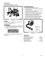
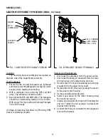
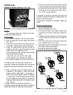
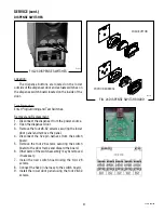
The BEEPER is located on the back side of the
component bracket assembly.
Test Procedures:
1. Enter Programming to verify the “Audible Alarm”
is activated. It will always beep when pressing
switches during program modes.
If activated, verify it is plugged correctly into J8 on the
control board.
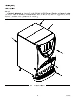
SERVICE(CONT.)
AUDIO INDICATOR (IMIX-3, 4 & 5 only)
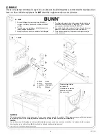
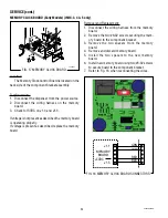
FIG. 2 AUDIO INDICATOR
BEEPER
P3250.25
FIG. 3 AUDIO INDICATOR
BEEPER
P3250.25
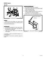
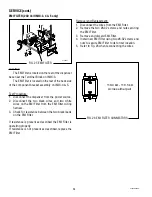
Removal and Replacement:
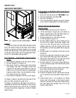
1. Disconnect the dispenser from power.
2. Disconnect the two pin connector from J8 of the
main control board.
3. Loosen two screws from underneath and remove
the component mounting bracket.
4. Remove the two #6-32 screws attaching the Audio
Indicator to the component mounting bracket.
5. Remove and discard the audio indicator.
6. Install new audio indicator using two #8-32 screws
to secure indicator to the component bracket.
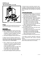
7. Refer to Fig. 3 when reconnecting the wires.
AUDIBLE ALARM ?
NO
EXIT
YES
Specifications:
SOUND PRESSURE LEVEL 90 dBA
RESONANT FREQUENCY 2800 Hz
RATED CURRENT 7 mA
RATED VOLTAGE 12 VDC
OPERATING VOLTAGE
3 - 28 VDC
BLK to J8-1
on Control Board
RED to J8-2
on Control Board
42032 060109
Содержание IMIX
Страница 10: ...10 42032 060109 NOTES ...
Страница 46: ...46 42032 060109 ...
Страница 48: ...48 42032 060109 ...


