


25
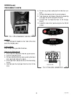
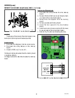
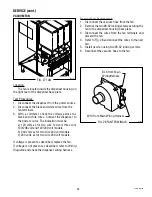
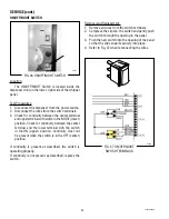
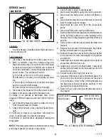
TEMPERATURE PROBE
FIG. 19 TEMPERATURE PROBE
P1665
SERVICE (cont.)
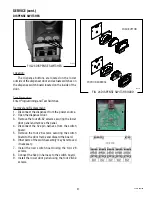
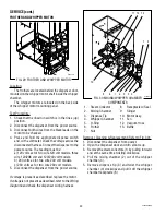
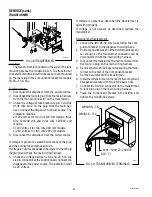
FIG. 20 TEMPERATURE PROBE
TEMP
RESISTANCE
VOLTAGE
READY
190° F
891 Ω
1.5VDC
87.0° C
ROOM
70° F
11.9k Ω
4.5VDC
21.1° C
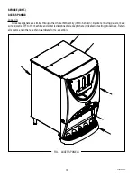
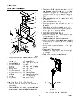
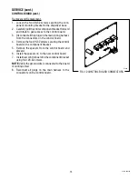
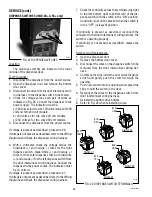
Location:
The temperature probe is located on the top of the
tank assembly.
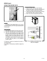
Test Procedure:
1. Disconnect the dispenser from the power source.
2. Remove the top rear cover.
3. With a voltmeter, back probe the connector from
the temperature probe.
4. Connect the dispenser to the power source.
5. See the chart for voltage readings.
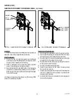
6. For continuity check, disconnect the dispenser
from the power source.
7. Disconnct the two pin connector from the dis-
penser main wiring harness.
8. With an ohmmeter, check for continuity across
the pins for the black and white wires.
9. See the chart for resistance readings.
10. Verify wiring to probe.
11. If readings are not present as described, replace
the temperature probe.
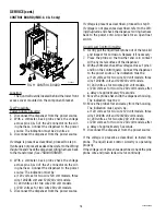
NOTE:
Some meters have difficulty measuring a sen-
sor either rapidly rising or falling in temperature.
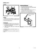
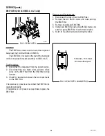
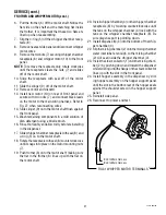
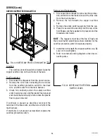
Removal and Replacement:
1. Disconnect the dispenser from the power source.
2. Remove the top rear cover.
3. Disconnct the two pin connector from the dis-
penser main wiring harness.
4. Remove the temperature probe by firmly pulling-
up on the tube at the tank lid. This will disengage
the grommet from the tank lid.
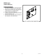
5. Slide a new grommet on to the new temperature
probe.
6. Insert the temperature probe through the hole
in the tank lid and press the grommet firmly and
evenly so that the groove in the grommet fits into
the tank lid.
7. Reconnect the two pin connector to the dispenser
main wiring harness.
BLK pin 1
WHI pin 2
42032 060109
Содержание IMIX
Страница 10: ...10 42032 060109 NOTES ...
Страница 46: ...46 42032 060109 ...
Страница 48: ...48 42032 060109 ...


