


24
SERVICE (cont.)
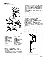
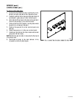
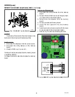
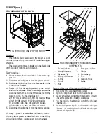
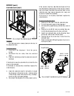
MEMORY CLOCK BOARD (Early Models) (IMIX-3, 4 & 5 only)
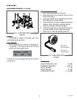
FIG. 17 MEMORY CLOCK BOARD
P3250.25
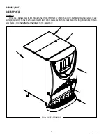
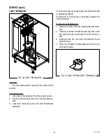
Location:
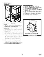
The Memory Clock Control Board is located on the
back side of the component bracket assembly.
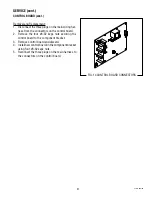
Test Procedure:
1. Disconnect the dispenser from the power source.
2. Disconnect the wiring harness on the memory
board.
3. Check for 5VDC on J1-4 and J1-5.
If voltage is not present as described the memory board
is operating properly.
If voltage is present as described, replace the memory
board.
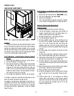
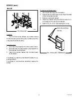
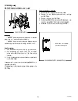
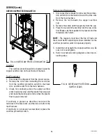
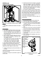
Removal and Replacement:
1. Disconnect the wiring harness from the memory
board.
2. Remove the two #6-32 screws securing the mem-
ory board to the component bracket.
3. Remove the two spacers from the memory
board.
4. Remove and discard memory board.
5. Install the two spacers to the new memory
board.
6. Install new memory board using two #6-32 screws
to secure board to the component bracket.
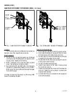
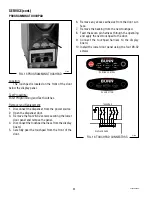
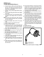
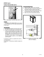
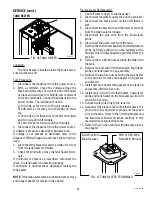
7. Refer to Fig. 18 when reconnecting the wires.
FIG. 18 MEMORY CLOCK BOARD CONNECTORS
MEMORY
BOARD
GRN
WHI
RED
BLK
+5VDC
J1-1
J1-5
42032 060109
Содержание IMIX
Страница 10: ...10 42032 060109 NOTES ...
Страница 46: ...46 42032 060109 ...
Страница 48: ...48 42032 060109 ...


