5
Installation
Logano plus SB325 – 6 720 806 328 (2013/07)
21
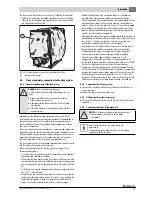
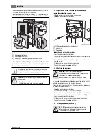
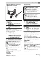
▶ Connect the drain hose [1] to the condensate drain with hose clips.
Fig. 17 Installing the neutralising system
[1]
Drain hose
5.6
Installing the minimum pressure switch and minimum
pressure limiter (accessories)
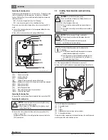
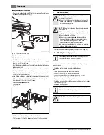
▶ Connect the minimum pressure switch or minimum pressure limiter
(with R ½ to R¼ adaptor) to the MDW connection on the boiler.
Fig. 18 Boiler connections
5.7
Installing the low water level limiter (accessory)
▶ Install the low water level limiter on the low water level limiter
connection pipe (
Fig. 18, page 21).
▶ If the LWI connection is not being used for the installation of a low
water level limiter, remove the plastic plug and close off the LWI
connection with a blanking plug.
5.8
Filling the boiler and checking connections for leaks
Before commissioning, check the heating system for tightness to ensure
that no leaks will occur during operation.
▶ Fill the heating system with water (
chapter 6.1, page 28
and chapter 6.2, page 29).
▶ Check all connections for leaks.
▶ Pressure test the heating system.
▶ Check flange connection and boiler connections for leaks.
▶ Check the pipework for leaks.
▶ After the tightness test, reinstate all components that were taken out
of operation. Ensure that all pressure, control and safety equipment is
working correctly.
5.9
Fitting the casing
5.9.1
Fitting the connection plates
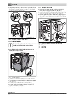
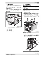
▶ Fit front tie bar (with trapezoid cut-out facing down) so that the
2 holes match up with the threaded pins at the top and fix with nuts.
▶ Fit rear tie bar (with trapezoid cut-out facing down) so that the 2 holes
match up with the threaded pins at the top and fix with nuts.
▶ Balance the front and rear connection plates with a spirit level.
Fig. 19 Locating and securing the front and rear tie-bars
You must ensure that the condensate generally runs via
the flue pipe into the boiler. If this is not possible, use
only stainless steel or plastic tees in the separate hose
line. With ceramic flue systems, fit a sludge separator
(sludge trap).
VK
M
VSL
MDW
AKO
RK2
RK1/EL
6 720 804 354-15.1ITL
AA
DANGER:
Risk of injury and/or system damage through
excess pressure when testing for leaks.
Pressure, control and safety equipment may be
damaged through excessive pressure.
▶ When carrying out the tightness test, ensure that no
pressure, control or safety equipment is fitted that
cannot be isolated from the boiler water chamber.
The test pressure level is subject to the system
components and to the heating system. Observe
country-specific regulations and standards.
The edge flanges on the cross-members must face
outwards and the front and rear cross members must be
horizontal and level with each other.
6 720 804 354-11.1ITL


