background image

9 | Help with faults

Büchi Labortechnik AG

76/88

Operation Manual UniversalExtractor E-800

9

Help with faults

9.1

Troubleshooting

Problem

Possible cause

Action

Flange lock is not in-
serted completely

The condenser is not in the
right position.

u

Move the condenser flange
a little bit until the lock falls
into the wholes.

Instrument does not
work

Instrument is not connected to
the power supply.

u

Make sure that the power
supply is connected and
switched on.

Method cannot
start

Solvent tank is full

u

Empty the solvent tank.

Protection shield is open

u

Close the protective shield.

No solvent present

u

Add solvent. See Chapter
"Adding solvent through the
condenser with a funnel",
page 69

Not enough solvent

u

Add solvent. See Chapter
"Adding solvent through the
condenser with a funnel",
page 69

Method stops

Cooling water flow is too low

u

Check the cooling water
connection and all hoses for
bends and remove them, if
necessary.

Cooling water sensor is defec-
tive (may be the coolant is
contaminated with algae, lime,
etc.)

u

Contact BUCHI Customer
Service.

Protection shield lifted

u

Close the protection shield.

Tank bottle full

u

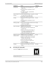
Empty the tank bottle. See
Chapter 8.2 "Removing the
tank bottle", page 73

Not enough solvent

u

Check for leaks.

u

Add solvent. See Chapter
"Adding solvent through the
condenser with a funnel",
page 69

Loss of solvent

Seals wrong, deformed or
damaged

u

Exchange the seals.

Incorrect positioning of the
beaker/ glassware and seals

u

Contact BUCHI Customer
Service.

Содержание E-800

Страница 1: ...UniversalExtractor E 800 Operation Manual 11593959 C en ...

Страница 2: ...rves the right to make changes to the manual as deemed necessary in the light of experience especially with respect to structure illustrations and technical details This manual is copyrighted Information from it may neither be reproduced distributed or used for competitive purposes nor made available to third parties The manufacture of any component with the aid of this manual without prior writte...

Страница 3: ... warning signs on the product 11 2 5 Protection devices 12 2 6 Residual risks 12 2 6 1 Hot surfaces 12 2 6 2 Empty beakers on heating plates 12 2 6 3 Mechanical damages 12 2 6 4 Glass breakage 13 2 6 5 Glass damages during extraction process 13 2 6 6 Overfilled extraction beakers 13 2 6 7 Spilled hazardous materials 13 2 6 8 Solvent leakages during extraction process 14 2 6 9 Incorrect function of...

Страница 4: ...let Warm Extraction with extraction glass chamber universal 18 3 1 6 Twisselmann Extraction with extraction glass chamber universal 18 3 1 7 Description of the analyte protection 18 3 2 Configuration 20 3 2 1 Front view with chamber heater 20 3 2 2 Front View without chamber heater 21 3 2 3 Rear view 22 3 2 4 Upper connections on the rear side 22 3 2 5 Lower connections on the rear side 23 3 2 6 I...

Страница 5: ...tion 34 5 9 Preparing the extraction glass chamber Economic Continuous Extraction 34 5 10 Installing the extraction glass chamber Economic Continuous Extraction 35 5 11 Preparing the extraction glass chamber universal 35 5 12 Installing the extraction glass chamber universal 36 5 13 Installing the protection shields 38 5 13 1 Installing two protection shields extraction glass chamber universal onl...

Страница 6: ...hamber heater Soxhlet Warm Hot and Twisselmann Extraction 55 6 6 9 Setting the Soxhlet valve open time of a method Soxhlet and Soxhlet Warm Extraction 56 6 6 10 Setting the rinse time of a method Soxhlet Soxhlet Warm Hot and Twisselmann Extraction 57 6 6 11 Setting the rinse heating level of a method Soxhlet Soxhlet Warm Hot and Twisselmann Extraction 57 6 6 12 Setting the number of dry steps 58 6...

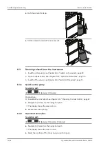
Страница 7: ...own the instrument 70 7 7 Exporting extraction parameters 70 7 7 1 Exporting extraction parameters without cloud connection 70 7 7 2 Exporting extraction parameters with cloud connection 71 8 Cleaning and servicing 72 8 1 Regular maintenance work 72 8 2 Removing the tank bottle 73 8 3 Draining solvent from the instrument 74 8 3 1 Switch on the pump 74 8 3 2 Open the tank valves 74 8 3 3 Switch of ...

Страница 8: ... buchi com contact 1 1 Warning notices in this document Warning notices warn you of dangers that can occur when handling the device There are four danger levels each identifiable by the signal word used Signal word Meaning DANGER Indicates a danger with a high level of risk which could result in death or serious injury if not prevented WARNING Indicates a danger with a medium level of risk which c...

Страница 9: ...cates the result of a correctly carried out instruction Mark up Explanation Window Software Windows are marked up like this Tab Tabs are marked up like this Dialog Dialogs are marked up like this Button Buttons are marked up like this Field names Field names are marked up like this Menu Menu item Menus or menu items are marked up like this Status Status is marked up like this Signal Signals are ma...

Страница 10: ...ded In particular the following applications are not permissible Use of the instrument in areas which require explosion safe apparatus Processing samples which could be caused to explode or ignite by impact friction heat or sparks e g explosives Use of the instrument with samples that react with solvent Use of the instrument with solvents containing peroxides Use of the instrument with other than ...

Страница 11: ...or the following aspects The device must be correctly installed commissioned operated and serviced Only suitably qualified staff may be assigned the task of performing the operations described in these operating instructions The staff must comply with the local applicable requirements and regulations for safe and hazard conscious working practices Safety related incidents that occur while using th...

Страница 12: ...s 2 6 1 Hot surfaces The surfaces of the device can become very hot If touched they can cause skin burns u Do not touch hot surfaces or else wear suitable protective gloves 2 6 2 Empty beakers on heating plates Empty beakers on active heating plates lead to very hot surfaces and can damage the instrument and the beakers u Remove empty beakers from the instrument u Deactivate heating positions not ...

Страница 13: ... components that are damaged u Do not use beakers which have been heated empty on a heating plate for more than 20 minutes 2 6 5 Glass damages during extraction process Glass damages during the extraction process can cause instrument damages caused by solvents coolant and fire u If fault occurs Switch off the device immediately Unplug the power cord Inform the operator Let the temperature of the i...

Страница 14: ...n Sensors u Do not cover or modify the analyte protection sensors u Only use clean beakers for extraction u Keep the reflector foils clean 2 6 10 Traces of dark extracts or residuals of extract foam Traces of dark extracts or residuals of extract foam on the beaker walls can lead to the incorrect functioning of the analyte protection sensor 2 7 Personal protective equipment Depending on the applic...

Страница 15: ...e 16 Hot Extraction with chamber heater See Chapter 3 1 4 Hot Extraction with extraction glass chamber universal page 17 Soxhlet warm Extraction with chamber heater See Chapter 3 1 5 Soxhlet Warm Extraction with extraction glass chamber universal page 18 Twisselmann Extraction with chamber heater See Chapter 3 1 6 Twisselmann Extraction with extraction glass chamber universal page 18 3 1 1 Economi...

Страница 16: ...d vapor rises up to the condenser condenses and drops into the extraction chamber with the sample The magnetic valve is open the solvent flows back into beaker the solvent is not collected Step 3 drying The solvent is heated vapor rises up to the condenser condenses and flows into tank The analyte remains in the beaker 3 1 3 Continuous Extraction with extraction glass chamber universal Step 1 extr...

Страница 17: ...up to the level sensor The analyte is extracted The solvent is heated in the extraction chamber vapor rises up to the condenser condenses and drops back into the extraction chamber The magnetic valve opens regularly to release a small portion of extract into the beaker Step 2 rinsing The solvent is heated vapor rises up to the condenser condenses and drops into the extraction chamber with the samp...

Страница 18: ...k into beaker the solvent is not collected Step 3 drying The solvent is heated vapor rises up to the condenser condenses and flows into tank The analyte remains in the beaker 3 1 6 Twisselmann Extraction with extraction glass chamber universal Step 1 extraction The sample is located in the extraction chamber The beaker contains the solvent The magnetic valve is closed the solvent is collected in t...

Страница 19: ...er the following situations Economic Continuou s Extraction Soxhlet Extraction Continuou s Extraction Hot Extraction Soxhlet Warm Extraction Twisselma nn Extraction Presence of beaker X X X X X X Presence of solvent Level check X X X X X X Extraction step X X X X X X Rinse step X X X X Dry step X X X X X X activation inert gas ...

Страница 20: ...w with chamber heater 4 3 5 6 13 12 1 2 7 8 9 11 10 Fig 2 Front view 1 Protection shield 2 Condenser rack 3 Chamber rack 4 Condenser tank bottle 5 Installation board 6 Tank bottle 7 Heating plate 8 Analyte protection sensor 9 Beaker rack 10 Chamber heater 11 Inert gas connection option 12 On Off master switch 13 Pro Interface ...

Страница 21: ...8 3 2 2 Front View without chamber heater 4 5 11 10 1 2 3 6 7 8 9 Fig 3 Front view 1 Protection shield 2 Condenser rack 3 Chamber rack 4 Condenser tank bottle 5 Tank bottle 6 Beaker rack 7 Installation board 8 Analyte protection sensor 9 Heating plate 10 On Off master switch 11 Pro Interface ...

Страница 22: ... See Chapter 3 2 4 Upper connec tions on the rear side page 22 2 Lower connections See Chapter 3 2 5 Lower connec tions on the rear side page 23 3 2 4 Upper connections on the rear side 1 2 3 4 Fig 5 Connections on the top 1 Standard BUCHI communication port COM 2 Standard BUCHI communication port COM 3 LAN port 4 Port for the cooling water valve ...

Страница 23: ... 6 Connections on the buttom 1 Coolant water solvent tank in marked IN 2 Solvent in marked TANK IN 3 Fuse 4 Power supply connection 5 Fuse 6 Inert gas connection option marked INERT 7 Coolant water out marked OUT 8 Exhaust marked EXHAUST 9 Coolant water in marked IN 10 Type plate 11 Coolant water solvent tank out marked OUT 12 Solvent out marked TANK OUT SOLVENT ...

Страница 24: ...00 only 3 Chamber rack Universal 4 FatExtractor E 500 only 5 Condenser rack Economic Continu ous Extraction 6 FatExtractor E 500 only 7 Chamber rack Economic Continuous Extraction 8 FatExtractor E 500 only 9 Beaker rack Universal 10 Solvent collector tube 11 Sensor plugs 12 Attachment clip for tube 13 Lift 3 3 Type plate The type plate identifies the instrument The type plate is located at the rea...

Страница 25: ...t voltage range 9 Serial number 10 Instrument name 11 Company name and address 3 4 Scope of delivery NOTE The scope of delivery depends of the configuration of the purchase order Accessories are delivered as per the purchase order order confirmation and delivery note 3 5 Technical data 3 5 1 UniversalExtractor E 800 Specification UniversalExtractor E 800 Power consumption 1780 W Connection voltage...

Страница 26: ...t of the solvent Number of extraction positions 6 Solvent tank volume 2 L Allowed inert gas pressure maximum 3 bar Max filling level Extraction glass chamber Universal 190 mL Max filling level Extraction glass chamber Universal LSV 315 mL Max working volumes Beaker 175 mL Max working volumes Beaker LSV 320 mL Language DE EN IT ES FR JA CN PL RU Method storage Pro interface 40 methods 3 5 2 Ambient...

Страница 27: ...erials Component Materials of construction Housing Steel 1 4301 304 with powder coating Exhaust Aluminium coated Protection shield PMMA GS Glass ware Borosilikat 3 3 Sealings glassware PTFE with FKM core Tank bottle Borosilikat 3 3 Tank bottle valve PTFE FFKM Sealing solvent connection PTFE Tubing FEP ...

Страница 28: ... to the carrier u Keep packaging for future transportation 4 2 Storage u Make sure that the ambient conditions are complied with see Chapter 3 5 Technical data page 25 u Wherever possible store the device in its original packaging u After storage check the device all glass components seals and tubing for damage and replace if necessary 4 3 Lifting the instrument WARNING Danger due to incorrect tra...

Страница 29: ...nsport and storage 4 Operation Manual UniversalExtractor E 800 29 88 Fig 9 Lifting the instrument u Lift the instrument this requires two persons each lifting at the points indicated on the left and right side of the instrument ...

Страница 30: ...ds such as direct solar radiation or other ignition source Do not place any flammable devices or substances close to the instrument as they could ignite due to the heat from the heating plates Make sure that cables tubes can be routed safely NOTE Make sure that the power supply can be disconnected at any time in an emergency 5 3 Establishing electrical connections NOTE Observe the regulatory provi...

Страница 31: ...ables make sure that they match the specifications on the type plate u Make sure that all connected devices are grounded u Make sure that the power plug is freely accessible at all times u Insert the power cable into the connection labeled Power IN on the back of the instrument u Insert the power plug into the power socket 5 4 Securing against earthquakes The instrument has an earthquake fixing po...

Страница 32: ...ch the drain tube in place with a hose clip 5 6 Connecting the solvent tubes to the condenser tank bottle NOTE Leave the connection nuts in place when disassembling Precondition R Make sure that the instrument is not connected to the power supply u Attach the inlet tube onto the connection marked TANK IN u Attach the drain tube onto the connection marked TANK OUT SOLVENT u Attach a solvent connect...

Страница 33: ...ach the inlet tube in place with a hose clip u Install the drain tube onto the connection marked CW TANK IN u Attach the drain tube in place with a hose clip u Attach the inlet tube onto the connection marked CW IN u Attach the drain tube onto the connection marked CW OUT u Make sure that the solvent collector circuit is complete See Chapter 11 1 Schematics page 79 5 8 Connecting inert gas option ...

Страница 34: ...ert gas tube onto the connection u Attach the inert gas connection nuts onto the extraction glas chamber u Connect the inert gas tube 5 9 Preparing the extraction glass chamber Economic Continuous Extraction NOTICE Make sure that the small gap of the sealing shows in the direction of the extraction glass chamber u Attach the sealing to the extraction glass chamber ...

Страница 35: ...page 43 u Prepare the extraction glass chamber Economic Continuous Extraction See Chapter 5 9 Preparing the extraction glass chamber Economic Continuous Extraction page 34 u Pull the chamber rack u Put the extraction glass chamber in the instrument u Push the chamber rack in the instrument 5 11 Preparing the extraction glass chamber universal NOTICE Risk of broken parts by using tools Using tools ...

Страница 36: ...e extraction glass chamber universal NOTICE Make sure that the small gap of the sealing shows in the direction of the extraction glass chamber u Attach the sealing to the extraction glass chamber The extraction glass chamber universal is pre pared 5 12 Installing the extraction glass chamber universal NOTICE An incorrect assembled extraction glass chamber can cause glass breakage u Install the ext...

Страница 37: ...e 43 u Prepare the extraction glass chamber universal See Chapter 5 11 Preparing the extraction glass chamber universal page 35 u Pull the chamber rack Precondition R Start with the extraction glass chamber on the left side R Make sure that the BUCHI Logo points to the front u Put the extraction glass chamber in the chamber rack u Turn the extraction glass chamber 45 counterclockwise ...

Страница 38: ...lass chamber locks at the hook u Connect the valve with the socket for sensor on the installation board u Push the chamber rack in the instrument 5 13 Installing the protection shields 5 13 1 Installing two protection shields extraction glass chamber universal only u Make sure that both protections shields fit together ...

Страница 39: ... at the point indicated u Put the rear protection shield on both sides into the rear slot at the same time u Put the front protection shield on both sides into the front slot at the same time 5 13 2 Installing one protection shield extraction glass chamber ECE only u Hold the protection shield on both sides at the point indicated ...

Страница 40: ...sides into the front slot at the same time 5 14 Preparing the condenser NOTICE Risk of broken parts by using tools Using tools for preparing the instrument can break parts u Tighten all parts with your hands NOTICE Make sure that the small gap of the sealing show in the direction of the condenser u Put the sealing on the bottom of the condenser u Attach the solvent connection nut with the seal to ...

Страница 41: ... E 800 41 88 u Connect the solvent collector tube NOTICE Do not use force to carry out this action step u Put the condenser in the condenser rack u Secure the condenser with the flange lock u Turn the condenser u Connect the solvent collector tube to the installation board ...

Страница 42: ...rd u Connect the condensers u Establish a condenser circuit u Make sure that the condenser circuit is complete See Chapter 11 1 Schematics page 79 5 15 Preparing the tank bottle NOTICE Risk of broken parts by using tools Using tools for preparing the instrument can break parts u Tighten all parts with your hands u Switch the On Off master switch to Off ...

Страница 43: ... Settings Precondition R Switch the On Off master switch to On u Navigate to the Settings submenu via the navigation path u Tap the action Select configuration ð The display shows a dialog with the selectable configurations u Tap the configuration according to the installed glass setup ð The configuration is selected ð The dialog box closes 5 17 Disassembling the condenser circuit u Disconnect the...

Страница 44: ...ctions u Remove the flange lock u Pull the condenser out of the condenser rack u Disconnect the solvent collector tube u Disconnect the solvent collector tube from the installation board 5 18 Mobile connection 5 18 1 Requirements for local network settings u The following port has to be enabled in the firewall settings on the internet gateway TCP HTTPS traffics through remote port 443 ...

Страница 45: ... Cloud connection manually NOTE If there is no DHCP server available enter the IP address gateway subnet mask and DNS server manually 5 18 2 Preparing the instrument for app using NOTICE Do not unplug the LAN cable while the unit is connected to the BUCHI Cloud Services u Connect the unit to the LAN local area network u Restart the unit Navigation path Settings Network u Navigate to Network u Acti...

Страница 46: ...ngs submenus or actions depending on the current operation 4 Function bar Shows functions that can be performed ac cording to the current operation 5 Stop button The extraction stops The valves close The heaters switch off The coolant keeps running 15 min 6 Navigation control Used for navigating the user interface Press ing the control performs the assigned func tion on the function bar 6 2 Functi...

Страница 47: ...on positions UP Up The lift moves up DOWN Down The lift moves down QR Code QR Code The display shows a QR Code which contains the data of all extraction pa rameters NEW New Saves a new setup LOAD Load Loads setup 6 3 Menu bar The menus are represented by symbols on the menu bar Navigation through the menus is by input controls The following menus are available Menu symbol Meaning Submenu Actions H...

Страница 48: ... 5 6 7 8 1 2 3 Fig 12 Home menu 1 Time remaining 2 Method 3 Status 4 Extraction position 5 Extraction time and heating level 6 Rinsing time and heating level 7 Drying time and heating level 8 Control buttons On the home menu the following control buttons are available Button Meaning Skips the actual step at the selected position Skips the actual step for all positions Aborts extraction on the sele...

Страница 49: ... Russian Polish Date Date input Enter in sequence Day month year Apply the settings by pressing OK Time Time input Enter in sequence Minutes hours Apply the settings by pressing OK Beeper Off On Setting for audible signal in response to input controls Display brightness Enter setting Display brightness level in 0 100 Configuration Choice of glassware The following glassware is available Universal ...

Страница 50: ...ld Valves Lift current Line voltage Line frequency Actors Open close The following settings can be changed Valves Soxhlet valves See Draining solvent from Extraction glass chamber Soxhlet Tank valves See Chapter 8 3 Draining solvent from the instrument page 74 Cooling water valve On Off Gas valve On Off option Heater On Off Pump solvent tank pump On Off Lift current u Tap up or down ð Display show...

Страница 51: ...data SeeChapter 7 7 Exporting extraction parameters page 70 Submenu Data use Action Option Explanation Number of extrac tions View Shows the number of extractions performed with the instrument Time of extraction View Shows the time the instrument per formed extractions 6 3 5 Solvent menu The solvent menu contains the available solvents for the extraction methods The solvent menu allows editing ind...

Страница 52: ... bar ð The new setup is created with a default name u Tap the new setup u Tap the function OK on the function bar ð The display shows a dialog with an alphanumeric input box u Enter a name for the set up u Tap the function Save on the function bar ð The name is saved ð The dialog box closes 6 6 Editing a method The Pro interface can save up to 40 extraction methods 6 6 1 Creating a new method Navi...

Страница 53: ...ation path u Tap the name of the method that you wish to edit ð The display shows the view Method u Tap the function Edit on the function bar u Tap the action Solvent ð The display shows a dialog with the selectable solvents u Tap the solvent you wish to use u Tap the function OK on the function bar ð The dialog box closes u Tap the function Save on the function bar ð The solvent is saved 6 6 4 Se...

Страница 54: ...he action Extraction time ð The display shows a dialog box with a numeric input box u Enter the value in the numeric input box u Tap the function OK on the function bar ð The dialog box closes u Tap the function Save on the function bar ð The value is saved 6 6 6 Setting the extraction cycles of a method Soxhlet and Soxhlet Warm Extraction The extraction time and the number of extraction cycles ar...

Страница 55: ...te ambient conditions WARNING Setting the heating level too high The consequences are device damage serious injuries or death u Use the pre set heating levels u Adjust the heating level to compensate the ambient conditions Navigation path u Navigate to the Method menu via the navigation path u Tap the name of the method that you wish to edit ð The display shows the view Method u Tap the function E...

Страница 56: ...e position of the level sensor and the sample structure Set the Soxhlet valve opening time so that the extraction glass chamber universal is completely emptied The following open times are available Open time Level sensor position Explanation short bottom The sample structure is easily releasing the solvent Hydrolysed sample in the glass sample tubes are extracted mid middle The sample structure i...

Страница 57: ... path u Navigate to the Method menu via the navigation path u Tap the name of the method that you wish to edit ð The display shows the view Method u Tap the function Edit on the function bar u Tap the action Rinse time ð The display shows a dialog box with a numeric input box u Enter the value in the numeric input box u Tap the function OK on the function bar ð The dialog box closes u Tap the func...

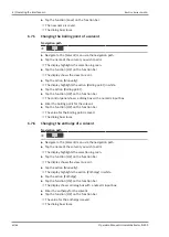
Страница 58: ...u Navigate to the Method menu via the navigation path u Tap the name of the method that you wish to edit ð The display shows the view Method u Tap the function Edit on the function bar u Tap the action Dry step u Tap the button ð A drying step is added u Tap the function Save on the function bar ð The new drying step is saved 6 6 13 Setting the analyte protection for a dry step NOTICE Risk of beak...

Страница 59: ...ry step starts under the following conditions the time for the dry step is reached the analyte protection triggers NOTE If the dry time is set to 0 and the analyte protection is activated the dry step continues until the analyte protection triggers Navigation path u Navigate to the Method menu via the navigation path u Tap the name of the method that you wish to edit ð The display shows the view M...

Страница 60: ... ð The display shows a dialog box with a numeric input box u Enter the value in the numeric input box u Tap the function OK on the function bar ð The dialog box closes u Tap the function Save on the function bar ð The heating level for the drying step is saved 6 7 Editing a solvent The solvent menu contains the predefined solvents for the extraction procedures Additional solvents can be added by f...

Страница 61: ...splay shows the view Solvent u Tap the action Manually ð The display highlights the action Chamber heater level white u Tap the action Chamber heater level ð The display shows a dialog box with a numeric input box u Enter a heating level for the solvent u Tap the function Save on the function bar ð The new name is saved ð The dialog box closes 6 7 4 Changing the heating level of a solvent Navigati...

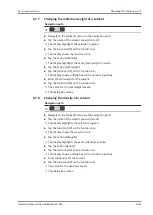
Страница 62: ...The control panel shows a dialog box with a numeric input box u Enter the boiling point for the solvent u Tap the function OK on the function bar ð The value for the boiling point is saved ð The dialog box closes 6 7 6 Changing the enthalpy of a solvent Navigation path u Navigate to the Solvent menu via the navigation path u Tap the name of the solvent you wish to edit ð The display highlights the...

Страница 63: ...umeric input box u Enter the mol weight for the solvent u Tap the function OK on the function bar ð The value for the mol weight is saved ð The dialog box closes 6 7 8 Changing the density of a solvent Navigation path u Navigate to the Solvent menu via the navigation path u Tap the name of the solvent you wish to edit ð The display highlights the selection in green u Tap the function OK on the fun...

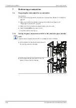
Страница 64: ...d installed See Chapter 5 15 Preparing the tank bottle page 42 R Make sure that no defective sealings or glass parts are used u Switch the On Off master switch to On ð The instrument is starting up 7 1 1 Putting the glass sample tube with frit in the extraction glass chamber NOTE Instead of glass sample tube with frit it is possible to insert a thimble u Put the holder for the glass sample tube wi...

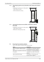
Страница 65: ...ting the optical sensor on the extraction glass chamber universal White line to the top of the sample Sample 7 2 Preparing the extraction positions There are three options to prepare the extraction positions Option Explanation Select a method for all extraction posi tions See Chapter 7 2 1 Selecting a method for all extraction positions page 66 Select different methods for each extrac tion positio...

Страница 66: ...es higher than 20 C Navigation path u Navigate to the Home menu via the navigation path u Tap the extraction position you wish to edit u The display shows a dialog box with selectable methods u Select a method u Tap the function OK on the function bar u Select a method for each extraction position by repeating the previous four steps 7 2 3 Selecting a programmed setup Navigation path u Navigate to...

Страница 67: ...ondition R The instrument has been prepared See Chapter 7 1 Preparing the instrument for an extraction page 64 R The extraction positions are prepared Chapter 7 2 Preparing the extraction positions page 65 R The sample is prepared in the glass sample tube or in the paper thimbles u Switch on the connected recirculating chiller or open the water tap u Pull the chamber rack out of the instrument u P...

Страница 68: ...ackground ð The instrument is starting the selected method u Wait until the solvent boils and condenses u Make sure that there are no leaks 7 4 Task during performing an extraction 7 4 1 Adding solvent through the condenser There are two possibilities to add solvent throught the condenser 1 with a dispenser see Chapter Adding solvent through the condenser with a dispenser page 68 2 with a funnel C...

Страница 69: ...the support solvent supply u Add solvent with a dispenser Adding solvent through the condenser with a funnel CAUTION Not correctly installed condenser A not correctly installed condenser can cause skin burns or a building fire u A beaker is placed under the position u An extraction glass chamber is installed at the position u The lift is in the lower position u Put a funnel on the condenser u Add ...

Страница 70: ...ther processing u If necessary remove solvent from the extraction glass chamber See Chapter 8 3 Draining solvent from the instrument page 74 u Switch off the connected recirculating chiller or close the water tap u Empty the solvent tank See Chapter 8 2 Removing the tank bottle page 73 7 6 Shutting down the instrument Navigation path Precondition R The extraction process has ended u Switch the On ...

Страница 71: ...ith the camera function of the App 7 7 2 Exporting extraction parameters with cloud connection Precondition R The App is installed on a mobile device R An extraction is finished R The instrument is connected via LAN cable See Chapter 5 18 Mobile connection page 44 u The extraction parameters are automatically transferred to the App ...

Страница 72: ...asive cleaning material u Make sure that the cleaning agent meets the requirements of the safety data sheets for the chemicals used u Make sure that the cleaning agent is compatible with the materials used See Chapter 3 5 Technical data page 25 u If you have any further questions contact BUCHI Customer Service Component Action Frequency Solvent tank u Empty the solvent tank See Chapter 8 2 Removin...

Страница 73: ...s on the instrument are legible u If they are dirty clean them Weekly Protection shields NOTICE Do not use Acetone u Wipe down the protection shields with a damp cloth u Make sure that they click into place If not replace the gliding elements See Replacing the gliding elements u If defective or damaged replace them Weekly Reflector foil for an alyte protection NOTICE Do not use any detergent u Swi...

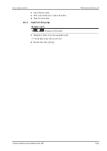
Страница 74: ...s page 74 3 Switch of the valves See Chapter 8 3 3 Switch of the pump page 75 8 3 1 Switch on the pump Navigation path Service Actors Precondition R A tank bottle is installed See Chapter 5 15 Preparing the tank bottle page 42 u Navigate to Actors via the navigation path ð The display shows the view Actors u Enable the action Pump 8 3 2 Open the tank valves Navigation path Service Actors Valves u ...

Страница 75: ...xtractor E 800 75 88 u Open the tank valve u Wait until all solvent is in the tank bottle u Close the tank valve 8 3 3 Switch of the pump Navigation path Service Actors u Navigate to Actors via the navigation path ð The display shows the view Actors u Disable the action Pump ...

Страница 76: ...vent through the condenser with a funnel page 69 Not enough solvent u Add solvent See Chapter Adding solvent through the condenser with a funnel page 69 Method stops Cooling water flow is too low u Check the cooling water connection and all hoses for bends and remove them if necessary Cooling water sensor is defec tive may be the coolant is contaminated with algae lime etc u Contact BUCHI Customer...

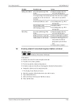
Страница 77: ...beaker directly onto the heating plate Beaker position is not active u Activate the beaker position Heater power is set too low u Adapt the heating power to the ambient conditions temperature level above sea u Choose correct solvent 9 2 Draining solvent from extraction glass chamber universal Navigation path Service Actors Valves Precondition R Solvent remains in the extraction glass chamber R The...

Страница 78: ...e all tubing and communication cables from the device 10 2 Disposal The operator is responsible for proper disposal of the instrument u When disposing of equipment observe the local regulations and statutory requirements regarding waste disposal u When disposing observe the disposal regulations of the materials used Materials used see Chapter 3 5 Technical data page 25 10 3 Returning the instrumen...

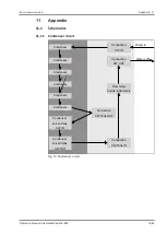
Страница 79: ...ematics 11 1 1 Condenser circuit Condenser Condenser Condenser Condenser Condenser Condenser Connection CW IN Connection CW OUT Flow meter inside instrument Connection CW Tank OUT Connection CW Tank IN Condenser solvent tank CW IN Condenser solvent tank CW OUT Water in Water out Fig 13 Condenser circuit ...

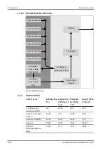
Страница 80: ...nk OUT solvent Connection Tank IN Condenser solvent tank IN solvent Condenser solvent tank OUT Fig 14 Solvent circuit 11 2 Solvent table Solvent name Boiling point C Evaporation enthalpy kJ mol Molecular weight g mol Density at 20 C g mL 2 Propanol Iso propanol iPrOH 82 39 85 60 1 0 78 Acetone Propanon AcMe 56 05 29 1 58 08 0 791 Acetonitril MeCN 81 65 29 75 41 05 0 78 Benzene 80 09 30 72 78 11 0 ...

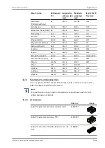
Страница 81: ...e 68 73 28 85 86 18 0 66 Petrolether 40 60 C 40 60 28 5 86 18 0 654 0 670 Tetrahydrofuran THF 65 29 81 72 11 0 89 Toluene 110 63 33 18 92 14 0 87 Water 100 40 65 18 0153 1 o Xylene 144 5 36 24 106 17 0 88 m Xylene 139 07 35 66 106 17 0 86 p Xylene 138 23 35 67 106 17 0 86 11 3 Spare parts and accessories Use only genuine BUCHI consumables and spare parts in order to ensure correct safe and reliabl...

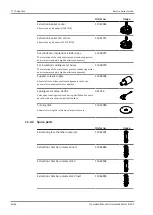
Страница 82: ...f the water hoses prevent condensing water and is recommended in high humidity environment 11069079 Support solvent supply Allows to fix the tubes of solvent dispensers to the con densers for convenient solvent addition 11068306 Cooling water valve 24VAC Valve opens cooling water feed during distillation Meant to be used with a vacuum controller interface 031356 Turning disk Allows for turning the...

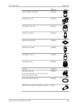
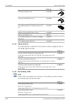
Страница 83: ...11067714 Condenser E 800 cpl 11067064 Condenser flange E 800 11067818 Condenser tank bottle 11065966 Tank bottle 2 L GL 45 11070509 Tank adapter PTFE 11064590 Joint clip 11070136 Soxhlet assembly cpl One part constiting of magnetic valve and level sensor for extraction glass chamber Soxhlet 11067065 Set of seals E 800 PTFE 2 pcs 11067483 Membrane with anchor for magnetic valve unit 037534 ...

Страница 84: ...ECE Includes 6 Extraction glass chamber ECE 11062499 set of draining tubes for ECE 11067479 11068488 Conversion kit ECE to Universal Includes 6 Universal glass chamber 11062501 set of draining tubes for Universal 11067477 11068494 Conversion kit from ECE to Universal LSV Includes 6 Universal LSV glass chamber 11062502 set of draining tubes for Univer sal 11067477 11068495 11 3 4 Recirculating chil...

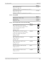
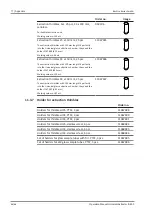
Страница 85: ... Order no Image Glass sample tubes with frit long 6 pcs The glass sample tubes with 150 mm length fit perfectly into the Universal glass extraction chamber Working volume 106 mL Filling volume 123 mL 11067815 Glass sample tubes with frit LSV long 6 pcs The glass sample tubes with 150 mm length fit perfectly into the Universal LSV glass extraction chamber Working volume 180 mL Filling volume 216 mL...

Страница 86: ... they need the holder 1167490 d33 mm Working volume 120 mL 11067446 Extraction thimbles 43 x 150 mm 25 pcs The extraction thimbles with 150 mm length fit perfectly into the Universal glass extraction chamber they need the holder 1167491 d 43 mm Working volume 182 mL 11067447 11 3 7 Holder for extraction thimbles Order no Holders for thimbles d25 PTFE 3 pcs 11067488 Holders for thimbles d33 PTFE 3 ...

Страница 87: ......
Страница 88: ...F 91 22 667 18986 india buchi com www buchi com in en Indonesia PT BUCHI Indonesia ID Tangerang 15321 T 62 21 537 62 16 F 62 21 537 62 17 indonesia buchi com www buchi com id in Japan Nihon BUCHI K K JP Tokyo 110 0008 T 81 3 3821 4777 F 81 3 3821 4555 nihon buchi com www buchi com jp ja Korea BUCHI Korea Inc KR Seoul 153 782 T 82 2 6718 7500 F 82 2 6718 7599 korea buchi com www buchi com kr ko Mal...

Отзывы: