background image

Operation 


SMART KNIT 

- 3.7 - 

Settings that affect the sensor detection features 

The 

IS3

 sensors do not simply detect the presence of the yarn, but they work as 

true micro-computers. They provide a digital signal output, which reflects the 
condition of the yarn within the detection area: 

Normal yarn running condition 

Yarn missing or broken condition 

The functioning of the sensor is based on the principle of image variation related to 
the shape of the yarn, detected by the small “camera”, which is implemented inside 
the sensor. Such a variation of image 

normally

 occurs only if the yarn is in actual 

movement inside the detection area, i.e. only if the yarn is running.  
Nevertheless, in certain cases, there may be some variation of image even though 
the yarn is not running normally, this is the case of a broken yarn oscillating inside 
the detection area. 
Finally there are other factors that can affect the detection activity of the sensors, 
like the size and type of yarn 

(silk, wool, acrylic, Lycra®, single filament nylon)

as the variation of the image depends on these factors as well. 
That’s why the microcomputer embedded in the sensor, processes the images 
provided by the “camera” by means of the sensor memory, which takes into 
account also these other influencing factors. 
The variables of this program are represented by the settings connected to the type 
of yarn used and to the specific application. 

Non-control time 

(D_CNTR)


Signaling tolerance for broken yarn

 (BROKE)


Signaling tolerance for uncut yarn 

(UNCUT)


Sensitivity 

(SENS)


Reaction Time 

(DELAY)


Start Frequency 

(F_START)


Stop Frequency 

(F_STOP)


Non-control time 

(D_CNTR) 

This parameter allows you to delay the beginning of the actual control process 
after the activation of SLOW EXT and FAST EXT inputs. It can be programmed 
to a value ranging between 

100

 ms and 

20 

s. 

Signaling tolerance for broken yarn 

(BROKE) 

This parameter allows you to establish the minimum duration of “broken or 
missing yarn” anomaly, to signal the 

(BROKE)

 condition. Such duration is tightly 

related to the actual machine operating speed. It can be programmed to a value 
ranging between 

10

 ms and 

1000 

ms with steps of 

10

 ms and between 

1000

 ms and 

16000

 ms with steps of 

100

 ms, or it can be disabled 

(OFF)

Signaling tolerance for uncut yarn 

(UNCUT) 

This parameter allows you to establish the minimum duration of “uncut yarn” 
anomaly, to signal the 

(UNCUT)

 condition. Such duration is tightly related to the 

actual machine operating speed. It can be programmed to a value ranging between 

10

 ms and 

1000 

ms with steps of 

10

 ms and between 

1000

 ms and 

16000

 ms with 

steps of 

100

 ms, or it can be disabled 

(OFF)

Sensitivity 

(SENS)


The SENS parameter allows the control of the sensor sensitivity level, depending 
on the article to be processed. 
It can be programmed to a value ranging between 

1

 and 

10

. The default value is 

4

Содержание IS3F-485

Страница 1: ...SMART KNIT IS3F 485 YARN CONTROL SYSTEM Operating Manual Rev 1 0 January 2006 ENGLISH ...

Страница 2: ... notice For any technical or commercial problem please contact your local BTSR dealer or call directly BTSR customer service center We will be glad to meet your needs Thank you for your trust and good job The product described herein is compliant with the requirements of 89 336 EEC EMC Directive and 73 23 EEC Low Voltage Directive All BTSR products are covered by patents and adopt exclusive profit...

Страница 3: ...ensors 3 6 Interpretation of the sensor signaling lights 3 6 Settings that affect the sensor detection features 3 7 Programming examples for F_START F_STOP and relevant sensor delays 3 8 Automatic adaptation of control parameters to the machine speed 3 9 Preliminary operations for using the SMART KNIT Terminal 3 10 Operating Sequences 3 11 Functions available from SETUP menu CONFIG 3 12 Functions ...

Страница 4: ...OW Configuration of Detection Parameters with Slow Ext Input Active 3 23 B3 P_FAST Configuration of Detection Parameters with Fast Ext Input Active 3 24 Display Signalings during the Control Process 3 25 Chapter 4 TROUBLESHOOTING AND MAINTENANCE Troubleshooting 4 1 Ordinary Maintenance 4 4 Repairs 4 4 Updating the Software Version on SMART Terminals 4 5 ...

Страница 5: ... control parameters set may also occur automatically through an internal timing related for instance to the initial ramp stage and normal rate stage of the machine respectively SMART KNIT combined with yarn control sensors IS3F 485 represents a complete and effective machine control system How to use this manual This Operation Manual is divided into 4 Chapters Chapter 1 Overview describes the main...

Страница 6: ...Introduction I 2 SMART KNIT Page intentionally left blank ...

Страница 7: ...fined by the control algorithm P_ABCD thus detecting possible deviations with respect to the above mentioned sequence and stopping the knitting machine when the detected errors exceed the set tolerance Special Features of SMART KNIT System The SMART KNIT system has a set of unique features which make it a true microcomputer dedicated to programming control of production and statistical analysis of...

Страница 8: ...tion Programmable Functions The systems allows programming either in global or selective way the sensor detection features Sensor Image Variation Frequency Sensitivity Reaction Time Tolerance etc Easy Monitoring and Fault Detection Besides the information provided on the graphical display of the SMART KNIT terminal each IS3 sensor has a red LED that when flashing indicates the location of the tech...

Страница 9: ... levels Signaling With integrated LEDs red green Sensor identification Through Touch Light Dimensions 25 x 35 x 10 mm Temperature range 0 60 C SM DIN KNIT Modules Power supply voltage 15 24 Vac or 24 Vdc 10 Absorption Typical 0 2 A Max 2 A 2 STOP Outputs Stop1 Stop2 NO NC relay contacts 0 24 Vac 3 Inputs Slow Ext Fast Ext Reset Ext NO NC relay contacts 0 24 Vdc Integrated Touch pad 3 push buttons ...

Страница 10: ... through SM DIN interface modules up to 8 Each module can manage up to 100 sensors distributed along 4 backbone lines The SM DIN modules communicate with SMART KNIT terminal via RS485 serial line Concerning all electrical systems it is a suggested rule to ensure that the ground cable GND is connected to the device support SM DIN modules Sensors connection ...

Страница 11: ...Technical Data and Installation SMART KNIT 2 3 SM DIN Modules Interconnection ...

Страница 12: ...ine Interface INPUTS Machine Interface OUTPUTS Chain 1 Sensors Chain 2 Sensors Chain 3 Sensors Chain 4 Sensors Max 100 sensors identified by means of Device function Setup Config menu SM DIN module nn identified by means of Edt function directly on SM DIN module Transformer ...

Страница 13: ... signaling the operating status and levels in which the system is working The following picture shows the location of the buttons and display zones that constitute the control panel of the system 1 ENTER button It allows you to activate the function selected from the menu indicated by the symbol to move to the programming of the displayed function or to confirm the setting value displayed on the m...

Страница 14: ...e necessary information to guide the operator step by step through the programming phase and interactive management of the system When the displayed lines refer to the menu items the selected one is indicated with the symbol The presence of a flashing cursor indicates the position where the operator can enter an alphanumeric character or variable setting which will replace the value currently disp...

Страница 15: ...e ENTER button while to do the opposite i e going from a lower to an upper level you must press the RESET button The level indication P1 P5 can be particularly useful during the initial phase when one is not yet familiar with the use of the programming functions For example if the system indicates P1 it is useless to press the RESET button as the system is already in the main menu and it is not po...

Страница 16: ... modules within the system 1 to 8 Communication speed Baudrate between SMART KNIT and SM DIN 115 2 or 57 6 Kbps Procedure During the normal machine operation Parameter 01 SM DIN module identification number To increase the value max 8 To decrease the value min 1 Parameter P02 Baudrate Always set 115 2 Kbps 3 sec To select 57 6 Kbps or 115 2 Kbps Default 115 2 Kbps ...

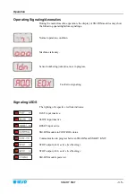
Страница 17: ...ndition Machine stationary Sensor numbering identification in progress Fault error signaling Signaling LEDS The lighting of respective red leds indicates FAST input inactive SLOW input inactive RESET input active SM DIN module in CONTROL status Communication in progress between SM DIN and SMART KNIT STOP output AL2 active led flashing STOP output AL1 active led flashing SM DIN module powered ...

Страница 18: ...o the control of any type of yarn application Optical interface of IS3 sensors The IS3 sensors have two signaling lights green LED red LED and a Touch Light optical button During the automatic numbering of the sensors flashing green LED touch the optical button to give the sensor the number shown in the devices configuration screen Interpretation of the sensor signaling lights Green LED ON Normal ...

Страница 19: ...nted by the settings connected to the type of yarn used and to the specific application Non control time D_CNTR Signaling tolerance for broken yarn BROKE Signaling tolerance for uncut yarn UNCUT Sensitivity SENS Reaction Time DELAY Start Frequency F_START Stop Frequency F_STOP Non control time D_CNTR This parameter allows you to delay the beginning of the actual control process after the activatio...

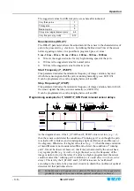
Страница 20: ...gnals that the yarn runs normally red LED ON It can be programmed to a value ranging between 1 and 10 Programming examples for F_START F_STOP and relevant sensor delays As the diagram shows if the F_START and F_STOP value is set low e g 2 then the sensor could detect the condition of running yarn even though the yarn is actually still or broken and is undergoing a light oscillation A and B areas o...

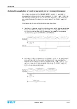
Страница 21: ...ication advantages such as Possibility of operating always with optimized parameters even if the machine features two different operating speeds for the processing of the same article providing that the machine itself is capable of providing two independent synchronization signals SLOW EXT and FAST EXT Possibility of using two different sets of parameters one for the ramp stage at low speed the ot...

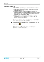
Страница 22: ...M DIN Interface Modules must turn On If the display does not light up then refer to Troubleshooting paragraph If the MACHINE message appears it means that the system correctly started the production control phase All the red Leds inside the buttons of SMART KNIT terminal as well as the Leds of SM DIN Interface Modules turn off except the CONTROL Leds If the ERROR RAM message appears on the screen ...

Страница 23: ...uncut yarns etc and stopping the machine when the detected errors exceed the set tolerances Performing the sensor test as well as the communication test between SMART KNIT terminal and SM DIN modules and between SM DIN modules and sensors in case of failures When the system is turned on after the initial diagnostic phase SMART KNIT immediately gets into monitoring phase CONTROL To access the setti...

Страница 24: ...Operation 3 12 SMART KNIT Functions available from SETUP menu CONFIG Functions available from SETUP menu P_ABCD P_SLOW P_FAST Main Menu Setup Programming Menu Main Menu Setup Programming Menu ...

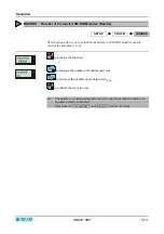
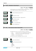
Страница 25: ...ber of SM DIN modules used to control the machine 1 to 8 to activate the function to increase the number of modules used nn to decrease the number of modules used nn to confirm the set value nn The number of configured modules must be consistent with the number of modules actually connected Otherwise the Program and Error labels will blink ...

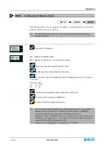
Страница 26: ...e cursor to move the cursor from aa field feeds to bb field sensors per feed or viceversa Allowed values aa 1 120 bb 1 6 to confirm the configured values and return to P3 menu to select the next function DEVICE to return to the P2 configuration menu The result obtained multiplying the number of feeds aa by the number of sensors per feed bb must be consistent with the number of SM DIN modules insta...

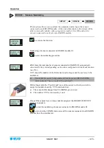
Страница 27: ...d by the system depending on the values configured with the Feeds function aa x bb YYY shows the number of the first sensor and subsequently the next one to be numbered Check that the sensor being numbered has the green LED FLASHING which indicates Sensor ready to be numbered With a finger skim the Touch Light area of the sensor to which you wish to assign the number shown by YYY and check that a ...

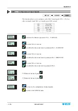
Страница 28: ...ET EXT IN 4 Not used IN 5 Not used to activate the function parameter IN 1 FAST EXT to select NC or viceversa to confirm the choice and move to parameter IN 2 SLOW EXT to select NC or viceversa to confirm the choice and move to parameter IN 3 RESET EXT to select NC or viceversa to confirm the choice and move to parameter IN 4 Parameter not used press Parameter not used press to move to the configu...

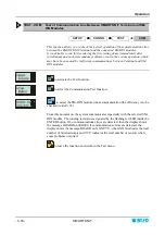
Страница 29: ...r ST 2 to select NO or viceversa to confirm the choice to move to the TEST function to return to CONFIG menu TEST Test Function and Sensor Firmware Update SETUP CONFIG TEST The TEST function allows you to perform 3 diagnostics sub functions COM Communication test between SMART KNIT and SM DIN FEEDS Test of sensors associated with the machine feeds SENSORS Test of individual sensors and a function ...

Страница 30: ...d SM DIN modules to activate the Test function to select the Communication Test function to select the SM DIN module whose communication line efficiency is to be checked initially 01 From this moment on the system communicates repeatedly with the selected SM DIN module The running test status is signaled by the flashing red LED inside the ENTER button If no communications errors are detected then ...

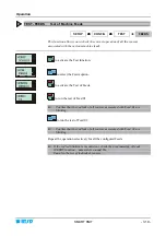
Страница 31: ...tion to activate the Test of Feeds to run the test of Feed 01 Confirm that the red leds of all sensors associated with Feed 01 are blinking to run the test of Feed 02 Confirm that the red leds of all sensors associated with Feed 02 are blinking Repeat the operation selectively for all the configured Feeds If the red led blinking is inconsistent check the programming of feeds FEEDS function paramet...

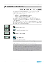
Страница 32: ...e SMART KNIT system display The operator shall simply select the number of the desired sensor confirming that the red LED of the selected sensor is flashing to activate the function test 2 times to select the Sensor option to access the Test of Sensors to select the next sensor to select the previous sensor Check that the Red LED of the selected sensor is blinking Repeat the operation selectively ...

Страница 33: ...tivate the Test function 3 times to access the UPG option nnn number of the first sensor to be upgraded mmm number of the last sensor to be upgraded to move the cursor from nnn field to mmm field or viceversa to increase the number pointed by the cursor to decrease the number pointed by the cursor to leave the function and return to the Test menu ...

Страница 34: ...sor to select the type of logical function to be assigned to the sensor AND function OR function blank no function sensor ignored to move the cursor one position to the right to move the cursor one position to the left to confirm the setting and return to the configuration menu P2 How to Set the Control Algorithm Example with 4 feeders 4 sensors per feed The four yarns must always run or not run s...

Страница 35: ...aragraph Settings that affect the sensor detection features to activate the function and to select in sequence the following parameters Delay Control Allowed values 100 ms 20 000 ms Broke tolerance prior to signal the broken yarn condition Allowed values 0010 ms 1 000 ms with steps of 10 ms and 1 000 ms 16 000 ms with steps of 100 ms Uncut tolerance prior to signal the uncut yarn condition Allowed...

Страница 36: ...aph Settings that affect the sensor detection features to activate the function and to select in sequence the following parameters Delay Control Allowed values 100 ms 20 000 ms Broke tolerance prior to signal the broken yarn condition Allowed values 0010 ms 1 000 ms with steps of 10 ms and 1 000 ms 16 000 ms with steps of 100 ms Uncut tolerance prior to signal the uncut yarn condition Allowed valu...

Страница 37: ...volved sensor Example SMART KNIT in control mode no failure detected Machine STOP due to broken yarn BROKE within the feed nn Machine STOP due to uncut yarn UNCUT within the feed nn Communication error between SMART terminal and device nn Inconsistency between number of sensors detected and number of sensors programmed Communication error between SMART KNIT and SM DIN module NN To restore the corr...

Страница 38: ...Operation 3 26 SMART KNIT Page intentionally left blank ...

Страница 39: ...stem off and on again If the problem persists contact your BTSR dealer The sensors numbering procedure fails the number YYY does not increase in the screen DEVICE YYY ZZZ Communications line problems Check that the sensors are correctly connected Check for locked sensors green and red LED simultaneously ON Turn off and on again the system If the problem persists replace the sensor If the problem p...

Страница 40: ...on SM DIN module nn Press If the problem persists turn the system off and on again If the problem persists replace the SM DIN module Message ERROR INPUT on display of SMART terminal The input signal configuration SLOW EXT FAST EXT is not consistent on all the SM DIN modules Check the wiring of input signals Message ERR_COM BOARDNN on display of SMART terminal Communication error between SMART term...

Страница 41: ... phase Check the programming parameters of BOARDS and FEEDS functions If the fault is not included in the above table please contact your local BTSR dealer giving a detailed description of the fault and the conditions in which it occurred When the BTSR Technical Service intervention is required before calling you are kindly recommended to take note of the code printed on the defective sensor s on ...

Страница 42: ... with an automatic compensation function which allows the detection features to remain unaffected even when some traces of dirt are present However it is suggested to clean the sensors periodically For cleaning purposes do not use solvent but rather a soft cloth dampened with neutral detergent or alcohol Repairs Any repair intervention on the SMART KNIT terminal or the SM DIN modules must be carri...

Страница 43: ... the 4 locking screws and remove the rear cover Fig 1 6 Using the IC extractor remove with care the Integrated Circuit from the socket located on the right top corner of PCB Fig 2 7 Place the Integrated Circuit containing the new software version over the socket paying attention to its correct orientation Fig 3 8 Applying a moderate and progressive pressure with both thumbs push the integrated cir...

Страница 44: ...Troubleshooting and Maintenance 4 6 SMART KNIT Page intentionally left blank ...

Страница 45: ...BTSR International S p A Via S Rita 21057 OLGIATE OLONA VA Tel 0331 323202 Fax 0331 323282 Internet www btsr com REV 1 0 01 06 DISTRIBUTOR ...

Отзывы: