3.3 - Installing the electronics box
M2007/3en
TCT-2301 Installation instructions
29
©BTG 2004
3.3.3
Connecting the measuring probe to the
electronics box
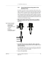
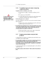
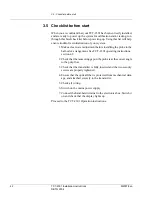
The optical connection is on the lower right side of the electronics box.
Remove the protective cover on the electronics box connector, and on the
optical connector on the probe. Note the position for the optical connec-
tor in fig 23. The connector fits only in one position. Make sure the O-
ring is mounted on the probe connector. Push the connector all the way
in. Try to turn the connector (this should not be possible) to verify that it
is in the end position. Secure the connection properly with the plastic nut.
Coil the extra optical fiber and secure it under the electronics box in order
to avoid the risk of mechanical damage.
!
Make sure the optical connector from the probe is positioned
correctly and pushed all the way in before securing it with the
plastic nut.
!
The optical fiber must not be coiled with a radius smaller than
50mm (2 in) Locate it so that is protected and not subject to risk of
mechanical damage.
The standard optical fiber is 10 m (33 ft). It is possible to use optical fiber
up to 40 m (131 ft) long. Contact your BTG sales engineer for more in-
formation regarding optional fiber lengths.
!
Do not cut the optical fiber.
Fig 23 Optical connection
1 Aluminum washer
2 Electronics box
3 Rubber sealing
4 Electronics box optical
connector
5 O-ring
6 Plastic nut
7 Probe optical connector
8 Optical fiber to probe

