


1.4 - System description
8
TCT-2301 Product introduction
M2007/3en
©BTG 2004
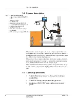
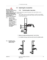
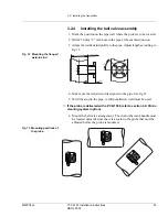
1.4 System description
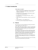
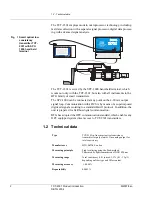
The system consists of a probe (1) connected by an optical fiber to an
electronics box (2) The probe contains only optical fibers. A ball valve
arrangement that is welded to the pipe system make it possible to remove
the probe without interrupting the process.
The electronics box contains electronics card, power supply, electrical
and optical connections. To set up the transmitter a hand-held terminal
(3) type SPC-1000 must first be connected (see fig 4).
The hand-held terminal allows the operator to set up and monitor the sys-
tem. It includes a liquid crystal display (LCD) with a touchscreen key-
pad.
1.5 Typical applications
•
Control of flotation systems or wash stages for de-inking of
recycled fibers
•
Control of screening and cyclone cleaning processes
•
Monitoring of TMP/CTMP steam and hot-water recovery
systems
CRC
1
3
5
2
8
4
9
7
6
Enter
Sample
Terminal
Total Consistency
Transmitter
TCT-2300
Fig 4 Typical control loop for
consistency control of the TCT-
2301
1 Measuring probe
2 Electronics box
3 Hand-held terminal SPC-1000
4 3/4 wire system for analog output
5 Controller/recorder (DCS)
6 Dilution water valve
7 Pulp chest with sufficient mixing
8 Stock pump
9 BTG sampling valve type MPS-1000


