- 76 -
PS-8810
DIGITAL SIGNAL PROCESSOR
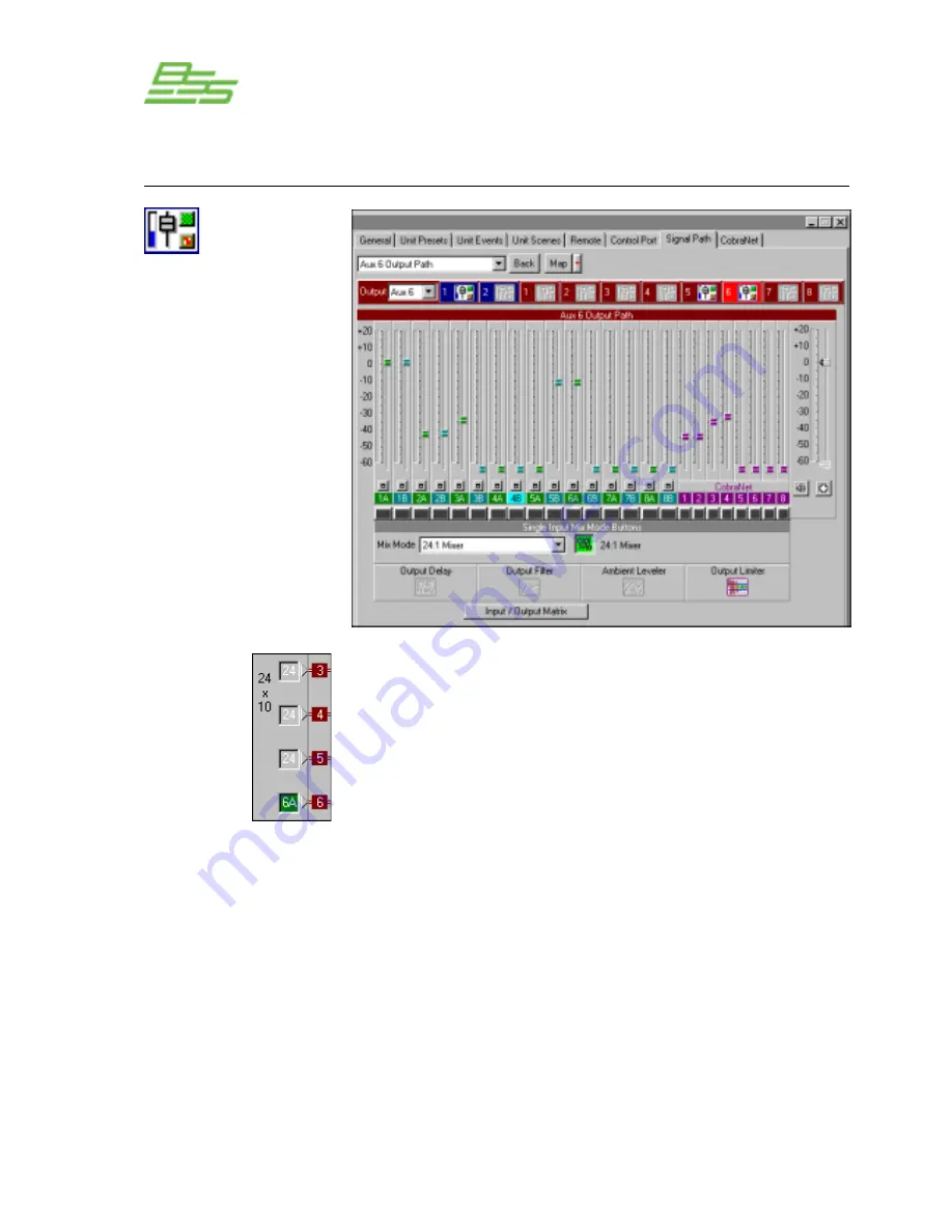
This panel is either accessed by clicking on one of the numbers
written in the 24x10 area or by clicking on the Output fader/mute/
polarity icon at the end of the Output processing section.
In addition to the output of each of the sixteen Input Processing
Sections, the eight CobraNet Inputs are fed to the Matrix Mixer,
providing a 24 Input by 10 Output fully independent crosspoint
mix as controlled by the Input/Output Matrix. Each of the ten
Output Processing Sections has independent fader control of all of
the inputs to the selected output, i.e. a 24:1 mixer, as shown above.
The Mix Mode drop down box is used for selecting exclusive
assignments between a particular input and output. This function
is repeated with the Single Input Mix Mode Buttons or the routing
can be reassigned to the 24:1 mixer.
The selected output channel displays the status of the Output
Processing Section objects and their parameters can be accessed
by clicking on these icons. There is also a button to quickly access
the Input/Output Matrix for further routing options.
Processing Functions
Output Path
Output Path
Содержание Prosys PS-8810
Страница 1: ...PS 8810 Digital Signal Processor Connect here first User Manual ...
Страница 12: ... 12 PS 8810 DIGITAL SIGNAL PROCESSOR ...
Страница 16: ... 16 PS 8810 DIGITAL SIGNAL PROCESSOR Controls Connectors Indicators ...
Страница 88: ... 88 PS 8810 DIGITAL SIGNAL PROCESSOR CobraNet ...
Страница 96: ... 96 PS 8810 DIGITAL SIGNAL PROCESSOR External Control ...
Страница 102: ... 102 PS 8810 DIGITAL SIGNAL PROCESSOR PS8810 IR Code Format ...
Страница 111: ... 111 PS 8810 DIGITAL SIGNAL PROCESSOR Reference Section ...
Страница 116: ... 116 PS 8810 DIGITAL SIGNAL PROCESSOR 19 0 Block Diagram ...
Страница 120: ... 120 PS 8810 DIGITAL SIGNAL PROCESSOR 21 0 User Notes ...
Страница 121: ... 121 PS 8810 DIGITAL SIGNAL PROCESSOR User Notes ...


