- 74 -
PS-8810
DIGITAL SIGNAL PROCESSOR
Processing Functions
Input/Output Matrix
system and the signal from Input Processing Section B for
recording.
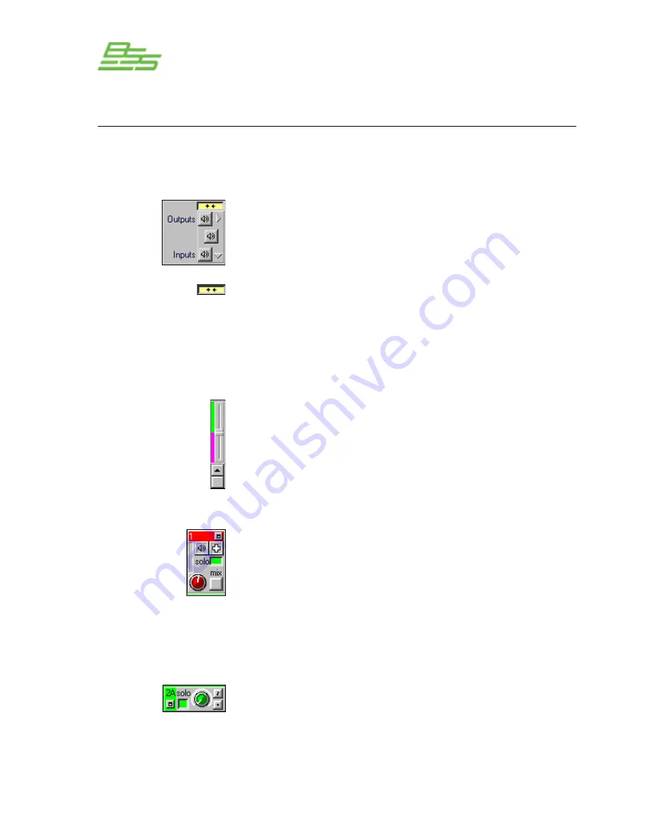
This panel at top left of the window has two functions; firstly it acts
as the overall mute cancel control, the top speaker icon unmuting
all the outputs, the bottom all the inputs and the middle both the
inputs and outputs simultaneously. Note that this clears any solo
assignments made for the selected channels.
Secondly, the small box with two arrows is the Matrix window
expand/compress button. With all the controls displayed for all the
channels this window can only be shown in full on a very high
resolution screen ( usefully 19” or above monitor). In order to give
access to all the channel controls on smaller screens the window
can be compressed to a more standard size by pressing this button.
In this situation an extra scroll bar control is displayed to the right of
the output channel controls, this is the default on opening the
window. Moving this slider alters the ratio of analogue channels
(green) that are displayed to the number of CobraNet channels
(pink). If the window is in its full size mode then this control is not
available and, the scrollbar for the analogue channels changes to a
green bar and a pink bar for the CobraNet channels.
The top row controls are for the output channels. The first two blue
topped columns are the Main outputs and the red are the Aux
outputs. These all have the same controls which include a mute
button (speaker icon), polarity switch (+ or - button), a solo control
(green for solo active), a gain control and a ‘Mix’ button that
reassigns any exclusive routings back to the 24:1 mixer level
controls. There is also a small signal indication meter. Clicking on
the small box in the coloured column header will leave the Matrix
and open the associated Output Path window.
The input channel controls are on the left of the Matrix and offer a
solo, input gain level adjustment, polarity switch and a mute
(shown by a small musical note symbol here). As usual the A and
B input processing paths are denoted by blue and green colouring.
Clicking in the small box in these coloured areas opens the Input
Path window linked to that channel.
Содержание Prosys PS-8810
Страница 1: ...PS 8810 Digital Signal Processor Connect here first User Manual ...
Страница 12: ... 12 PS 8810 DIGITAL SIGNAL PROCESSOR ...
Страница 16: ... 16 PS 8810 DIGITAL SIGNAL PROCESSOR Controls Connectors Indicators ...
Страница 88: ... 88 PS 8810 DIGITAL SIGNAL PROCESSOR CobraNet ...
Страница 96: ... 96 PS 8810 DIGITAL SIGNAL PROCESSOR External Control ...
Страница 102: ... 102 PS 8810 DIGITAL SIGNAL PROCESSOR PS8810 IR Code Format ...
Страница 111: ... 111 PS 8810 DIGITAL SIGNAL PROCESSOR Reference Section ...
Страница 116: ... 116 PS 8810 DIGITAL SIGNAL PROCESSOR 19 0 Block Diagram ...
Страница 120: ... 120 PS 8810 DIGITAL SIGNAL PROCESSOR 21 0 User Notes ...
Страница 121: ... 121 PS 8810 DIGITAL SIGNAL PROCESSOR User Notes ...


