Bryant EVOLUTION V 189BNV 13 Скачать руководство пользователя страница 6

6

NOTE:

Install branch circuit disconnect of adequate size per NEC

to handle unit starting current. Locate disconnect within sight from
and readily accessible from unit, per Section 440--14 of NEC.

Route Ground and Power Wires

Remove access panel to gain access to unit wiring. Extend wires

from disconnect through power wiring hole provided and into unit
control box.

!

WARNING

ELECTRICAL SHOCK HAZARD

Failure to follow this warning could result in personal injury

or death.
The unit cabinet must have an uninterrupted or unbroken

ground to minimize personal injury if an electrical fault

should occur. The ground may consist of electrical wire or

metal conduit when installed in accordance with existing

electrical codes.

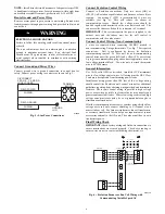
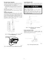
Connect Ground and Power Wires

Connect ground wire to ground connection in control box for
safety. Connect power wiring to contactor as shown in Fig. 5.

DISCONNECT
PER N. E. C. AND/OR
LOCAL CODES

TERMINAL

BLOCK

GROUND
LUG

FIELD GROUND

WIRING

FIELD POWER

WIRING

A14028

Fig. 5 -- Line Power Connections

Connect Evolution Control Wiring

Connect to Evolution connections. Only two wires (AB) or

(GN,YL) to Evolution capable indoor unit (furnace or fan coil) are
required.

Connecting C (WT) is recommended if wires are

available (see Fig. 6). This will reduce the chance of
communication issues.

Unused low voltage wires should be

bundled together and terminated with a wire nut at each end. The
end nearest the indoor coil should be connected to C terminal.

IMPORTANT

: This system requires the power supplied to the

outdoor unit, and the indoor unit, for the wall control to
communicate with the outdoor unit.

Connect Control Wiring-- Non--Communicating

4 wires are required when connecting 189BNV models to

non--communicating 2--stage thermostats. Use Fig. 7 For required
connections.

Unit is configured by factory for Evolution

communicating control. To wire unit for non--communicating

control, disconnect the green (GN) and yellow (YL) wires from
4--pin green communication plug and connect appropriate wires to

low voltage terminal block. Use wire nuts to attach thermostat
wire to LVCH harness.

General Information

Use 18--20 solid AWG color--coded, insulated (35

_

C minimum)

wire for low voltage control wires. All wiring must be NEC Class
2 and must be separated from incoming power leads.
Installations using greater than 200 feet of low voltage wiring
should consult the Evolution wall control manual for additional

guidelines regarding daisy chaining wiring method and terminating

resistors. Never route control wiring in parallel to high voltage
power wires when possible as electrical noise may transfer and

generate nuisance fault codes. Where low voltage control and high
voltage wires must cross paths, do so at perpendicular angles to

eliminate transferred noise.
If further communication issues exist, consider using shielded low
voltage wires and only connect shielding to C terminal at end

nearest indoor coil. Use furnace transformer, fan coil transformer,
or accessory transformer for control power requirement of system

accessories external to the OD unit. The outdoor unit has its own

transformer power.

Final Wiring Check

IMPORTANT:

Check factory wiring and field wire connections to

ensure terminations are secured properly. Check wire routing to

ensure wires are not in contact with tubing, sheet metal, etc.

D

C

B

A

Wall Control

HP or AC

OA

T

R

Y

O

W

C

HUM

C

Humidifier

24v

ac

Furnace or Fan Coil

’C’ connection optional

Sheild Cable

D not required

Unused Wires

WT

YL

GN

D

C

B

A

A150776

Fig. 6 -- Evolution Furnace or Fan Coil Wiring with

Communicating Variable Speed AC

Содержание EVOLUTION V 189BNV 13

Страница 1: ...nstall on Solid Level Mounting Pad 3 Step 3 Clearance Requirements 3 Step 4 Operating Ambient 4 Step 5 Elevate Unit 4 Step 6 Making Piping Connections 4 Step 7 Make Electrical Connections 5 Step 8 Com...

Страница 2: ...erant equipment WARNING ELECTRICAL SHOCK HAZARD Failure to follow this warning could result in personal injury or death Before installing modifying or servicing system main electrical disconnect switc...

Страница 3: ...or specific applications and for R 22 retrofit Step 1 Check Equipment and Job Site Unpack Unit Move to final location Remove carton taking care not to damage unit Inspect Equipment File claim with shi...

Страница 4: ...eration Do not leave system open to atmosphere any longer than minimum required for installation POE oil in compressor is extremely susceptible to moisture absorption Always keep ends of tubing sealed...

Страница 5: ...re to follow this caution may result in equipment damage or improper operation Never use the system compressor as a vacuum pump Refrigerant tubes and indoor coil should be evacuated using the recommen...

Страница 6: ...g 189BNV models to non communicating 2 stage thermostats Use Fig 7 For required connections Unit is configured by factory for Evolution communicating control To wire unit for non communicating control...

Страница 7: ...r on Control Board Jumper Wire Required for Single Stage C BLU YEL R RED BLK A160118 O O RVS Cooling O B W2 W1 W1 Heat Stage 3 W W1 W2 Heat Cool Stage 1 Y1 W2 Y1 Y1 Heat Cool Stage 2 Y Y2 Y Y2 Y2 Fan...

Страница 8: ...non communicating furnaces set airflows to 350 400 cfm nominal ton in high stage and 70 80 percent of high stage airflow in low stage Step 9 Install Accessories No refrigeration circuit accessories ar...

Страница 9: ...Select Line Set Length Vapor Line Diameter CAUTION UNIT OPERATION HAZARD Failure to follow this caution may result in improper unit operation For new installations only Add additional refrigerant due...

Страница 10: ...nverter Motor Operational Control MOC then outputs the three phase PWM signal and frequency that gently ramps the compressor speed up to stage 2 and then will adjust to the demanded speed The gentle r...

Страница 11: ...s to stabilize before declaring a properly charged system If the indoor temperature is below 70 F 21 11 C or the outdoor temperature is not in the favorable range adjust charge for line set length abo...

Страница 12: ...g Mode 189BNV024B Fig 20 Charging in Cooling Mode 189BNV025 Fig 21 Charging in Cooling Mode 189BNV036 Fig 22 Charging in Cooling Mode 189BNV037 Fig 23 Charging in Cooling Mode 189BNV048 Fig 24 Chargin...

Страница 13: ...tion of the procedure 2 Force system to operate in high stage by creating a large differential between room temperature and set point on thermostat Use multi meter to verify that 24 VAC is present bet...

Страница 14: ...r NOTE A hissing sound may be heard during the equalization process This is normal TROUBLESHOOTING Systems Communication Failure If communication is lost with the User Interface UI the Green LED will...

Страница 15: ...r low pressure lockout check the refrigerant charge and indoor airflow cooling Brown Out Protection If the line voltage is less than 187V for at least 4 seconds the Compressor and OD fan goes to 0 rpm...

Страница 16: ...and distributor See Fig 31 for proper placement See Table 4 for proper resistances A14328 Fig 30 Outdoor Coil Thermistor OCT Attachment On Distributor Tube OAT Thermistor must be locked in place with...

Страница 17: ...e Unit Size Resistance Ohms 13 24B 21 2 25 36 37 48 49 60 11 1 Status Codes Unit may occasionally become unresponsive due to certain combinations of previous fault codes There may not be anything wron...

Страница 18: ...18 Utility Relay A13414 Fig 34 Variable Speed Control Board with optional Utility Relay...

Страница 19: ...19 Table 6 Fault Codes...

Страница 20: ...ig low side retard S Use hoses with 700 psig service pressure rating S Leak detectors should be designed to detect HFC refrigerant S Puron refrigerant as with other HFCs is only compatible with POE oi...

Отзывы: