Bryant EVOLUTION V 189BNV 13 Скачать руководство пользователя страница 5

5

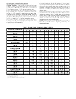
Outdoor Unit Connected to Factory--Approved Indoor

Unit

Outdoor unit contains correct system refrigerant charge for

operation with factory--approved, AHRI--rated indoor units when
connected by 15 ft. (4.57 m) of field--supplied or factory--accessory

tubing, and factory--supplied filter drier. Check refrigerant charge
for maximum efficiency.

NOTE:

If the indoor furnace coil width is more than the furnace

casing width, refer to the indoor coil Installation Instructions for
transition requirements.

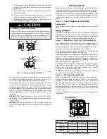
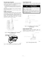
Install Liquid--Line Filter Drier Indoor

Refer to Fig. 3 and install filter drier as follows:

1. Braze 5--in. (127 mm) liquid tube to the indoor coil.
2. Wrap filter drier with damp cloth.
3. Braze filter drier to above 5--in. (127 mm) liquid tube.
4. Connect and braze liquid refrigerant tube to the filter drier.

CAUTION

!

UNIT DAMAGE HAZARD

Failure to follow this caution may result in unit damage or

improper operation.
Installation of filter drier in liquid line is required.

A05178

Fig. 3 -- Liquid--Line Filter Drier

Refrigerant Tubing connection Outdoor

Connect vapor tube to fitting on outdoor unit vapor service valves
(see Table 1).

Sweat Connections

CAUTION

!

UNIT DAMAGE HAZARD

Failure to follow this caution may result in equipment

damage or improper operation.

S

Use a brazing shield

S

Wrap service valves with wet cloth or heat sink material.

Use refrigerant grade tubing. Service valves are closed from factory
and ready for brazing. After wrapping service valve with a wet

cloth, braze sweat connections using industry accepted methods
and materials. Consult local code requirements. Refrigerant tubing

and indoor coil are now ready for leak testing. This check should

include all field and factory joints.

Evacuate Refrigerant Tubing and Indoor Coil

CAUTION

!

UNIT DAMAGE HAZARD

Failure to follow this caution may result in equipment

damage or improper operation.
Never use the system compressor as a vacuum pump.

Refrigerant tubes and indoor coil should be evacuated using the
recommended deep vacuum method of 500 microns. The alternate

triple evacuation method may be used. See Service Manual for
triple evacuation method. Always break a vacuum with dry

nitrogen prior to opening the refrigerant system for servicing.
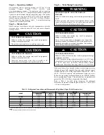
Deep Vacuum Method

The deep vacuum method requires a vacuum pump capable of
pulling a vacuum of 500 microns and a vacuum gauge capable of

accurately measuring this vacuum depth. The deep vacuum method
is the most positive way of assuring a system is free of air and

liquid water. (See Fig. 4)

500

MINUTES

0

1

2

3

4

5

6

7

1000

1500

LEAK IN

SYSTEM

VACUUM TIGHT

TOO WET
TIGHT

DRY SYSTEM

2000

MI

CRONS

2500

3000

3500

4000

4500

5000

A95424

A95424

Fig. 4 -- Deep Vacuum Graph

Final Tubing Check

IMPORTANT:

Check to be certain factory tubing on both indoor

and outdoor unit has not shifted during shipment. Ensure tubes are
not rubbing against each other or any sheet metal. Pay close
attention to feeder tubes, making sure wire ties on feeder tubes are
secure and tight.

Step 7 — Make Electrical Connections

!

WARNING

ELECTRICAL SHOCK HAZARD

Failure to follow this warning could result in personal

injury or death.
Do not supply power to unit with compressor terminal box

cover removed.

Be sure field wiring complies with local and national fire, safety,
and electrical codes, and voltage to system is within limits shown

on unit rating plate. Contact local power company for correction of

improper voltage. See unit rating plate for recommended circuit
protection device.

NOTE:

Operation of unit on improper line voltage constitutes

abuse and could affect unit reliability. See unit rating plate. Do not

install unit in system where voltage may fluctuate above or below

permissible limits.

NOTE:

Use copper wire only between disconnect switch and unit.

Содержание EVOLUTION V 189BNV 13

Страница 1: ...nstall on Solid Level Mounting Pad 3 Step 3 Clearance Requirements 3 Step 4 Operating Ambient 4 Step 5 Elevate Unit 4 Step 6 Making Piping Connections 4 Step 7 Make Electrical Connections 5 Step 8 Com...

Страница 2: ...erant equipment WARNING ELECTRICAL SHOCK HAZARD Failure to follow this warning could result in personal injury or death Before installing modifying or servicing system main electrical disconnect switc...

Страница 3: ...or specific applications and for R 22 retrofit Step 1 Check Equipment and Job Site Unpack Unit Move to final location Remove carton taking care not to damage unit Inspect Equipment File claim with shi...

Страница 4: ...eration Do not leave system open to atmosphere any longer than minimum required for installation POE oil in compressor is extremely susceptible to moisture absorption Always keep ends of tubing sealed...

Страница 5: ...re to follow this caution may result in equipment damage or improper operation Never use the system compressor as a vacuum pump Refrigerant tubes and indoor coil should be evacuated using the recommen...

Страница 6: ...g 189BNV models to non communicating 2 stage thermostats Use Fig 7 For required connections Unit is configured by factory for Evolution communicating control To wire unit for non communicating control...

Страница 7: ...r on Control Board Jumper Wire Required for Single Stage C BLU YEL R RED BLK A160118 O O RVS Cooling O B W2 W1 W1 Heat Stage 3 W W1 W2 Heat Cool Stage 1 Y1 W2 Y1 Y1 Heat Cool Stage 2 Y Y2 Y Y2 Y2 Fan...

Страница 8: ...non communicating furnaces set airflows to 350 400 cfm nominal ton in high stage and 70 80 percent of high stage airflow in low stage Step 9 Install Accessories No refrigeration circuit accessories ar...

Страница 9: ...Select Line Set Length Vapor Line Diameter CAUTION UNIT OPERATION HAZARD Failure to follow this caution may result in improper unit operation For new installations only Add additional refrigerant due...

Страница 10: ...nverter Motor Operational Control MOC then outputs the three phase PWM signal and frequency that gently ramps the compressor speed up to stage 2 and then will adjust to the demanded speed The gentle r...

Страница 11: ...s to stabilize before declaring a properly charged system If the indoor temperature is below 70 F 21 11 C or the outdoor temperature is not in the favorable range adjust charge for line set length abo...

Страница 12: ...g Mode 189BNV024B Fig 20 Charging in Cooling Mode 189BNV025 Fig 21 Charging in Cooling Mode 189BNV036 Fig 22 Charging in Cooling Mode 189BNV037 Fig 23 Charging in Cooling Mode 189BNV048 Fig 24 Chargin...

Страница 13: ...tion of the procedure 2 Force system to operate in high stage by creating a large differential between room temperature and set point on thermostat Use multi meter to verify that 24 VAC is present bet...

Страница 14: ...r NOTE A hissing sound may be heard during the equalization process This is normal TROUBLESHOOTING Systems Communication Failure If communication is lost with the User Interface UI the Green LED will...

Страница 15: ...r low pressure lockout check the refrigerant charge and indoor airflow cooling Brown Out Protection If the line voltage is less than 187V for at least 4 seconds the Compressor and OD fan goes to 0 rpm...

Страница 16: ...and distributor See Fig 31 for proper placement See Table 4 for proper resistances A14328 Fig 30 Outdoor Coil Thermistor OCT Attachment On Distributor Tube OAT Thermistor must be locked in place with...

Страница 17: ...e Unit Size Resistance Ohms 13 24B 21 2 25 36 37 48 49 60 11 1 Status Codes Unit may occasionally become unresponsive due to certain combinations of previous fault codes There may not be anything wron...

Страница 18: ...18 Utility Relay A13414 Fig 34 Variable Speed Control Board with optional Utility Relay...

Страница 19: ...19 Table 6 Fault Codes...

Страница 20: ...ig low side retard S Use hoses with 700 psig service pressure rating S Leak detectors should be designed to detect HFC refrigerant S Puron refrigerant as with other HFCs is only compatible with POE oi...

Отзывы: