


13
Step 13 — Pumpdown & Evacuation
CAUTION
!
ENVIRONMENTAL HAZARD
Failure to follow this caution may result in environmental
damage.
Federal regulations require that you do not vent refrigerant to
the atmosphere. Recover during system repair or final unit
disposal.
If this system requires either a Pump Down or Evacuation for any
reason, the procedures below must be followed:
Pump Down -- Evolution Communicating
Because this system is inverter controlled, compressor, suction
pressure transducer, conventional procedure cannot be used to
“pump down” and isolate the refrigerant into the outdoor unit. The
UI (User Interface) has provisions to assist in performing this
function.
1. Connect gauges to 189BNV liquid and vapor service valve
ports to monitor operating pressures during and at comple-
tion of the procedure.
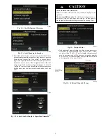
2. In the advanced menu of the UI, go to Checkout > Pump-
down
3. Select mode to pump down in (COOL). Set desired time
period. Default time period for the procedure is 120 min-
utes.
4. Select Start on UI to begin the pump--down process. Unit
will begin running in selected mode after a brief delay.
5. Close the liquid service valve.
6. The unit will run in selected mode with the low pressure
protection set to indicate pump--down is complete when the
suction pressure drops below 10 psig. Compressor protec-
tions are still active to prevent damage to the compressor or
inverter (high pressure, high current, high torque, etc.) .
7. Once system indicates pump--down complete or failure to
complete shutdown, close vapor service valve.
8. A small quantity of charge will remain in isolated section of
system dependent on ambient temperature and overall sys-
tem charge. This charge must be manually recovered. A
recovery system will be required to remove final quantity of
refrigerant from indoor coil and line set.
9. Remove power from indoor and outdoor unit prior to ser-
vicing unit.
Pump Down – Using 2--stage Thermostat
(Non--Communicating)
Because this system has an inverter controlled compressor, suction
pressure transducer, conventional procedure cannot be used to
“pump down” and isolate the refrigerant into the outdoor unit.
1. Connect gauges to 189BNV liquid and vapor service valve
ports to monitor operating pressures during and at
completion of the procedure.
2. Force system to operate in high stage by creating a large
differential between room temperature and set point on
thermostat. Use multi--meter to verify that 24 VAC is
present between C and Y1 and Y2 terminals at outdoor unit.
3. Close the liquid service valve.
4. The unit will continue to run until high or low pressure
switches open. Close vapor service valve once compressor
shuts down.
5. Remove power from indoor and outdoor unit prior to
servicing unit.
6. A quantity of charge will remain in isolated section of
system dependent on ambient temperature and overall
system charge. This charge must be manually recovered. A
recovery system will be required to remove final quantity of
refrigerant from indoor coil and line set.
Evacuation and recovery of refrigerant from 189BNV
1. Connect gauges to 189BNV liquid and vapor service valve
ports to monitor operating pressures during and at comple-
tion of the procedure. Attach recovery system or vacuum
pump to gauge set as needed for the service procedure. The
service valves must be open to evacuate the unit through the
line set service ports.
Evacuation and recovery of refrigerant from 189BNV
when using non--communicating thermostat
1. Connect gauges to 189BNV liquid and vapor service valve
ports to monitor operating pressures during and at
completion of the procedure. Attach recovery system or
vacuum pump to gauge set as needed for the service
procedure. The service valves must be open to evacuate the
unit through the line set service ports.
MAJOR COMPONENTS
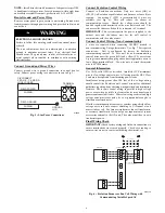
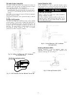
Variable speed Control Board
A160120
Fig. 26 -- AOC (Application Operational Control) Board
The AOC board is located in the lower right hand side of inverter
tray. It’s functions include:
S
Compressor speed control
S
Outdoor fan motor control
S
Crankcase heater operation
S
Pressure switch monitoring
S
Time Delays
S
Pressure Transducer measurements
S
PEV control (pressure equalizer valve)
S
Temperature measurements
S
Inverter communication and control
Inverter
The inverter is located inside the control box. This is an air--cooled
device that communicates with the control board and drives the
compressor and fan motor to the demanded RPM. The inverter is
always powered with line voltage since no contactor is used. The
inverter changes the line voltage to DC volts and then recreates 3
phase sine waves that vary in frequency to drive the compressor
and fan motor at the desired RPM.


