


4
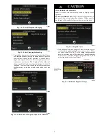
Step 4 — Operating Ambient
The minimum outdoor operating ambient is 40
_
F (4.4
_
C) with
Evolution
Connex
Control,
55
_
F
(12.8
_
C)
with
non--communicating systems. The maximum outdoor operating
ambient is 115
_
F (46.1
_
C). Compressor protections will prevent
operation below minimum ambient temperature range. The system
may operate in cooling up to 125
_
F (52
_
C) (52C) with significant
reduced capacity cutback above 115
_
F (46.1
_
C). Refer to Product
Data “Detailed Cooling Capacity” table.
Low ambient cooling
operation is not currently available.
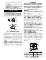
Step 5 — Elevate Unit
Elevate unit per local climate and code requirements to provide
clearance above estimated snowfall level and ensure adequate
drainage of unit.
CAUTION
!
UNIT OPERATION HAZARD
Failure to follow this caution may result in equipment
damage or improper operation.
Do not allow water and/or ice to build up in base pan.
CAUTION
!
UNIT OPERATION HAZARD
Failure to follow this caution may result in equipment
damage or improper operation.
Locate the unit in such a way that it is stable in all
circumstances including adverse weather conditions.
Step 6 — Make Piping Connections
!
WARNING
PERSONAL INJURY AND UNIT DAMAGE
HAZARD
Failure to follow this warning could result in personal injury or
death.
Relieve pressure and recover all refrigerant before system
repair or final unit disposal. Use all service ports and open all
flow--control devices, including solenoid valves.
CAUTION
!
UNIT DAMAGE HAZARD
Failure to follow this caution may result in equipment
damage or improper operation.
Do not leave system open to atmosphere any longer than
minimum required for installation. POE oil in compressor is
extremely susceptible to moisture absorption. Always keep
ends of tubing sealed during installation.
UNIT DAMAGE HAZARD
Failure to follow this caution may result in equipment damage
or improper operation.
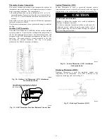
If ANY refrigerant tubing is buried, provide a 6 in. (152.4 mm)
vertical rise at service valve. Refrigerant tubing lengths up to 36
in. (914.4 mm) may be buried without further special
consideration. Do not bury lines longer than 36 in. (914.4 mm).
CAUTION
!
Outdoor units may be connected to indoor section using accessory
tubing package or field--supplied refrigerant grade tubing of correct
size and condition. For tubing requirements between 80 -- 100 ft.
(24.38 -- 30.48 m), capacity and performance losses can occur.
Follow the pipe sizing recommendations in the 189BNV Product
data to manage these losses. This unit shall not be installed with
greater than 100 ft (30.48 m) of equivalent line length.
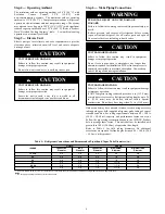
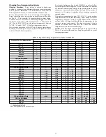
Refer to Table 1 for field tubing diameters. No additional
accessories are required for line lengths between 80 -- 100 ft. (24.4
-- 30.5 m) on this product.
Table 1 – Refrigerant Connections and Recommended Liquid and Vapor Tube Diameters (in.)
189BNV
LIQUID
VAPOR
*
Connection
Diameter
Tube
Diameter
Connection
Diameter
Max (Rated)
Diameter
Minimum Tube
Diameter
13, 24B
3/8
3/8
3/4
3/4
5/8
25
3/8
3/8
3/4
7/8
5/8
36
3/8
3/8
3/4
7/8
5/8
37
3/8
3/8
7/8
1---1/8
5/8
48, 49
3/8
3/8
7/8
1---1/8
3/4
60
3/8
3/8
7/8
1---1/8
3/4
*
Units are rated with 25 ft. (7.6 m) of lineset. See Product Data sheet for performance data when using different size and length line sets.
Notes
:
1. Do not apply capillary tube indoor coils to these units.


