background image

13

CB

MODEL 

PL8

FORCED

DEFROST

J2

1

BRN

RED

SEC1

SEC2

PWM2

PWM1

INVER

TER 

PL1

PL2

RVS

CC

PL11

PL4

PL6

OCT

OAT

SPT

OST

A B C NO

USE

UTIL

LS Y

C

O

COMM STATUS

YEL

BLU

EXV

PL5

PL3

HPS

Utility Interface*

A11544

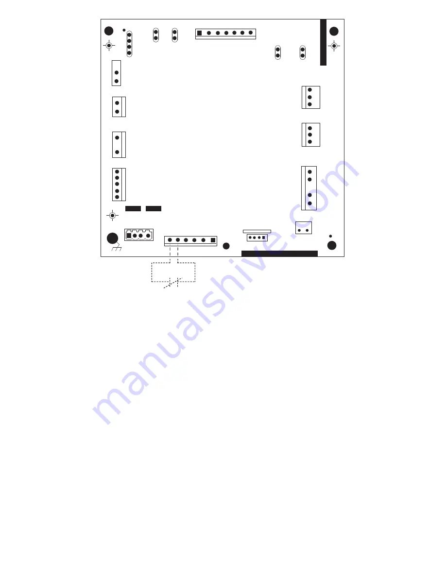
Fig. 16 -- Variable Speed Control Board

with optional Utility Relay

Содержание 180CNV024

Страница 1: ...distributor or branch for information or assistance The qualified installer or agency must use factory authorized kits or accessories when modifying this product Refer to the individual instructions...

Страница 2: ...susceptible to lineset transmitted noise inside the dwelling and in extreme cases tubing breakage CAUTION INSTALLATION RECOMMENDATIONS In some cases noise in the living area has been traced to gas pu...

Страница 3: ...shipment is damaged or incomplete Locate unit rating plate on unit corner panel It contains information needed to properly install unit Check rating plate to be sure unit matches job specifications St...

Страница 4: ...ft 24 38 m substantial capacity and performance losses can occur Follow the pipe sizing recommendations in the 180CNV Product data to manage these losses Refer to Table 1 for field tubing diameters Re...

Страница 5: ...heck should include all field and factory joints Evacuate Refrigerant Tubing and Indoor Coil CAUTION UNIT DAMAGE HAZARD Failure to follow this caution may result in equipment damage or improper operat...

Страница 6: ...r has an internal crankcase heater Furnish power to the unit a minimum of 24 hr before starting the unit for the first time To furnish power to heater only set thermostat to OFF and close electrical d...

Страница 7: ...e energized to run at lowest cooling demand If this does not satisfy cooling demand the system will ramp up in stages until it satisfies the demand After coping with the higher demand the unit returns...

Страница 8: ...ons S Two minute time delay to return to standby operation from last valid communication S One minute time delay of outdoor fan at termination of cooling mode when outdoor ambient is greater than or e...

Страница 9: ...th the control board and drives the compressor to the demanded RPM When the contactor closes it powers the inverter with line voltage The inverter changes the line voltage to 410 volts DC 3 phase and...

Страница 10: ...n 187v for at least 4 seconds the contactor and fan relay are de energized Compressor and fan operation are not allowed until voltage is a minimum of 190v The control will flash the appropriate fault...

Страница 11: ...e CAUTION UNIT DAMAGE HAZARD Failure to follow this caution may result in equipment damage or improper operation In order to minimize the ambient influence make sure the thermistor curved surface hugs...

Страница 12: ...long flashes indicating the second digit of the error code The short flash is 0 25 seconds ON and the long flash is 1 0 second ON Time between flashes is 0 25 seconds Time between short flash and firs...

Страница 13: ...1 BRN RED SEC1 SEC2 PWM2 PWM1 INVERTER PL1 PL2 RVS CC PL11 PL4 PL6 OCT OAT SPT OST A B C NO USE UTIL LS Y C O COMM STATUS YEL BLU EXV PL5 PL3 HPS Utility Interface A11544 Fig 16 Variable Speed Control...

Страница 14: ...14 Table 7 Troubleshooting...

Страница 15: ...ld hose when charging into suction line with compressor operating S Manifold sets should be 700 psig high side and 180 psig low side with 550 psig low side retard S Use hoses with 700 psig service pre...

Страница 16: ...iscontinue or change at any time specifications or designs without notice and without incurring obligations E2017 Bryant Heating Cooling Systems 7310 W Morris St Indianapolis IN 46231 Edition Date 12...

Отзывы: