9
If the indoor temperature is above 80
_
F (26.67
_
C), and the
outdoor temperature is in the favorable range, adjust system charge
by weight based on line length and allow the indoor temperature to
drop to 80
_
F (26.67
_
C) before attempting to check system charge
by subcooling method as described above.
If the indoor temperature is below 70
_
F (21.11
_
C), or the outdoor
temperature is not in the favorable range, adjust charge for line set
length above or below 15ft (4.57 m) only. Charge level should then
be appropriate for the system to achieve rated capacity. The charge
level could then be checked at another time when the both indoor
and outdoor temperatures are in a more favorable range. This
ensures maximum efficiency and reliability.
Step 13 — Pumpdown
If this system requires a Pumpdown for any reason, the procedures
below must be followed:
Because this system has an inverter controlled, compressor, and a
suction pressure transducer conventional procedure cannot be used
to “pump down” and isolate the refrigerant into the outdoor unit.
The wall control has provisions to assist in performing this
function.
1. Connect gages to 180CNV liquid and vapor or suction cap-
illary service ports to monitor operating pressures during
and at completion of the procedure.
2. In the advanced menu of the wall control, go to Refrigerant
Charge > Pumpdown
3. Select mode to pump down in COOL. COOL mode allows
refrigerant to be isolated in outdoor unit. Set desired time
period. Default time period for the procedure is 120 min-
utes.
4. Select Start on wall control to begin the pumpdown process.
Unit will begin running in selected mode after a brief delay.
5. Close the liquid service valve.
6. The unit will run in selected mode with the low pressure
protection set to indicate pumpdown is complete when the
suction pressure drops below 0 psig. Compressor protec-
tions are still active to prevent damage to the compressor or
inverter (high pressure, high current, high torque, scroll
temperature, etc.) .
7. Once system indicates pumpdown complete or failure to
complete shutdown, close vapor service valve.
8. If pumpdown does not complete due to compressor safety
shutdown, a recovery system will be required to remove fi-
nal quantity of refrigerant from indoor coil and line set.
9. Remove power from indoor and AC unit prior to servicing
unit.
MAJOR COMPONENTS
Variable speed Control Board
The AC control board controls the following functions:
S
Compressor speed
S
Contactor operation
S
Outdoor fan motor operation
S
Low ambient cooling
S
Crankcase heater operation
S
Pressure switch monitoring
S
Time Delays
S
Pressure Transducer
S
Inverter communication and control
Inverter
The inverter is located inside the control box. This is an air--cooled
device that communicates with the control board and drives the
compressor to the demanded RPM. When the contactor closes, it
powers the inverter with line voltage. The inverter changes the line
voltage to 410 volts DC 3--phase, and varies the frequency to drive
the compressor at the desired RPM.
NOTE
: Manually closing the contactor will not cause the unit to
operate. The unit must be operated with an Evolution Control. A
standard thermostat will allow operation only in the emergency
mode (high speed heating or cooling).
Variable Speed Compressor
This unit contains a variable speed compressor that has a wide
operating range. It operates on 410vdc provided by the inverter.
This compressor can only be operated by the specific inverter
supplied with the unit.
EQUIPMENT DAMAGE HAZARD
Failure to follow this caution may result in equipment damage
and/or improper operation.
Do not attempt to apply line voltage directly to the
compressor. This will destroy the compressor.
CAUTION
!
Field control Connections
For normal operation use the ABCD Evolution connections only.
Only two wires, AB are required. See Fig. 14. Discrete inputs (Y,C,
O) are available for emergency operation if the Evolution Bus is
not in operation.
Pressure Transducer (SPT)
A 5 VDC output low pressure transducer that provides a 0--5 VDC
data for interpretation by the control board for a 0 to 200 psig
range of pressure at the suction tube. This interpreted pressure data
is then intelligently used by the control board for low pressure
cut--out, loss of charge management, compressor overall envelope
management, oil circulation management and lubrication
management. (See Fig. 13.)
Compressor Control Contactor
The contactor has a 24 volt coil. The electronic control board
controls the operation of the contactor.
TROUBLESHOOTING
Systems Communication Failure
If communication with the Evolution control is lost with the User
Interface (UI), the control will flash the appropriate fault code (see
Table 7). Check the wiring to the User Interface and the indoor and
outdoor units and power.
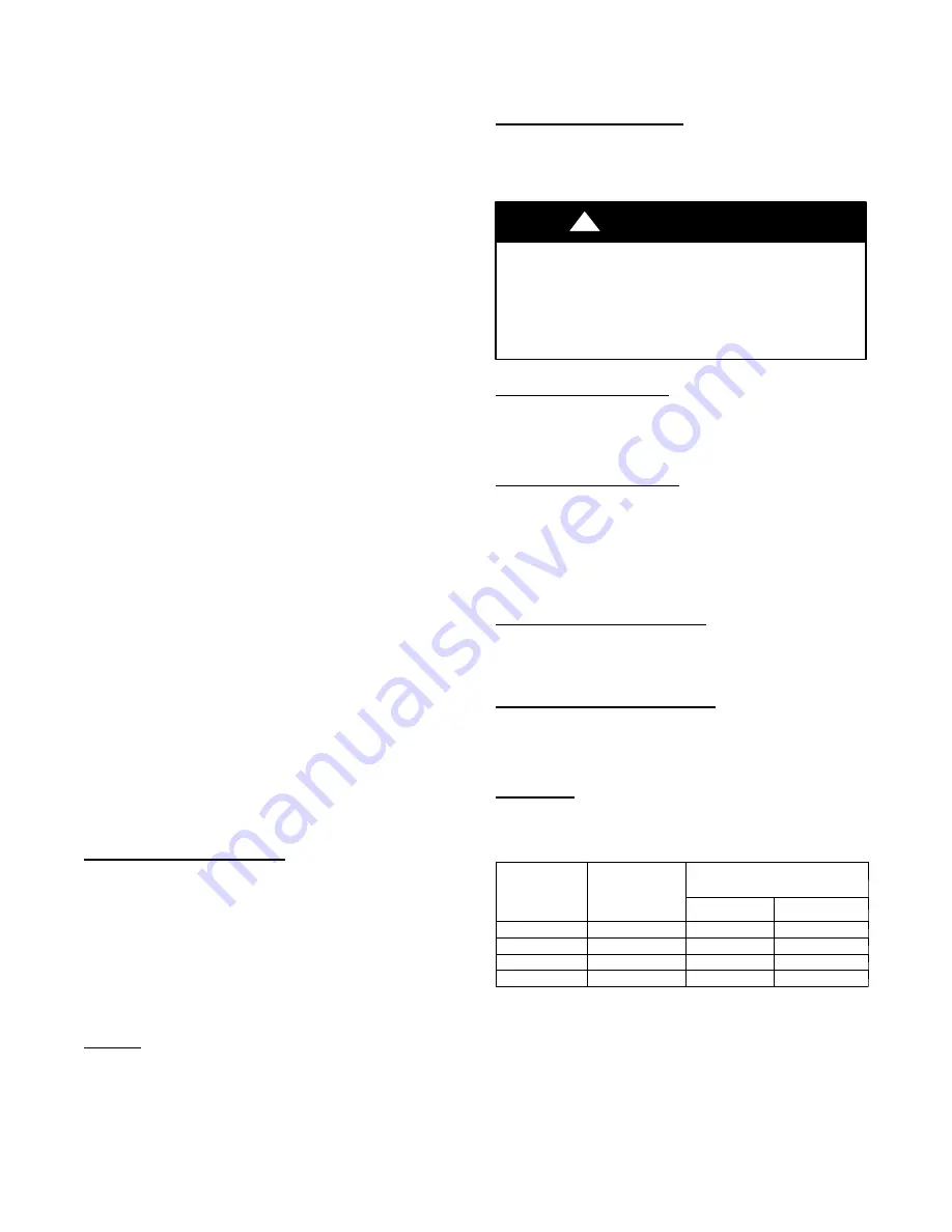
Model Plug
Each control board contains a model plug. The correct model plug
must be installed for the system to operate properly (see Table 3).
Table 3 – Model Plug Information
MODEL
NUMBER
MODEL PLUG
NUMBER
PIN RESISTANCE
(K---ohms)
Pins 1---4
Pins 2---3
180CNV024
HK70EZ011
5.1K
150K
180CNV036
HK70EZ012
5.1K
180K
180CNV048
HK70EZ013
5.1K
220K
180CNV060
HK70EZ014
5.1K
270K
The model plug is used to identify the type and size of unit to the
control.
On new units, the model and serial numbers are input into the
board’s memory at the factory. If a model plug is lost or missing at
initial installation, the unit will operate according to the
information input at the factory and the appropriate error code will
flash temporarily. An RCD replacement board contains no model
and serial information. If the factory control board fails, the model
plug must be transferred from the original board to the replacement
board for the unit to operate.
Содержание 180CNV024
Страница 14: ...14 Table 7 Troubleshooting...


