


III-
35
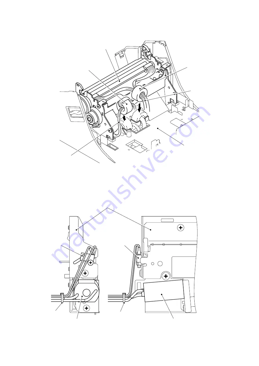
(3) Put the ferrite cores of the head cables and tape feed motor harness into the place
provided on the under cover as shown in the figure below.
Fig. 3.2-15 Installing the Mecha ASSY and Cutter unit ASSY (3)
(4) Bind the harnesses of the cutter unit ASSY with the fastening band.
Note: Be sure to bind the harnesses securely so that there is no looseness.
Fig. 3.2-16 Installing the Mecha ASSY and Cutter unit ASSY (4)
Cutter unit ASSY
Fastening band
Cover left sensor ASSY
Cutter motor ASSY
Mecha ASSY
Under cover
Tape feed motor harness
Head cable
Ferrite core
Ferrite core
Fastening band
Cover left sensor ASSY
Cutter motor ASSY
Содержание QL-1050
Страница 1: ...P touch SERVICE MANUAL MODEL QL 1050 ...
Страница 92: ...6 5 Tape sensor check Click the Tape sensor check button Fig 6 ...
Страница 97: ...11 7 Fan check 1 Click the Fan check button Fig 12 ...
Страница 102: ...16 5 Click the Quit cut test button to finish the cut test mode Fig 18 ...
Страница 115: ...August 2006 8V7104BE0 Printed in Japan ...


