


III-
15
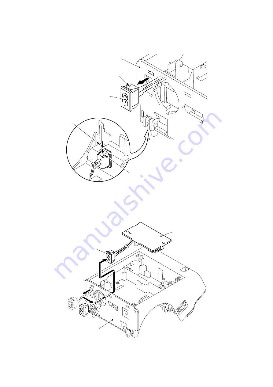
(7) Release the hooks on both sides of the inlet and pull the inlet to the direction of the arrow
as shown in the figure below to remove it.
For the hook on the lower side of the inlet, turn the under cover upside down and press
the hook from the hole on the under cover.
Fig. 3.1-17 Removing the Power Supply PCB and Main PCB (7)
(8) Pull the inlet out of the hole of the fan to remove it and remove the power supply PCB from
the machine.
Fig. 3.1-18 Removing the Power Supply PCB and Main PCB (8)
Under cover
Hook
Inlet
Hole
Hook
Inlet
Under cover
Power Supply PCB
Содержание QL-1050
Страница 1: ...P touch SERVICE MANUAL MODEL QL 1050 ...
Страница 92: ...6 5 Tape sensor check Click the Tape sensor check button Fig 6 ...
Страница 97: ...11 7 Fan check 1 Click the Fan check button Fig 12 ...
Страница 102: ...16 5 Click the Quit cut test button to finish the cut test mode Fig 18 ...
Страница 115: ...August 2006 8V7104BE0 Printed in Japan ...


